A busbar conductive connection terminal

A technology for connecting terminals and busbars, applied in the direction of contact parts, etc., can solve the problems of excessive temperature rise at the terminals, easy to loose, poor contact, etc., to reduce the risk of expansion and looseness, increase the contact area, and enhance the conductivity. Effect

Active Publication Date: 2016-02-10
ZHUZHOU CSR TIMES ELECTRIC CO LTD
View PDF5 Cites 0 Cited by
  • Summary
  • Abstract
  • Description
  • Claims
  • Application Information

AI Technical Summary

Problems solved by technology

Conventional connection terminals are prone to loosening when heated or squeezed during assembly, resulting in poor contact; especially for large outer diameter copper rings, copper pad riveting or thin copper ring riveting, heat is more likely to cause riveting loosening, during use It is easy to cause poor contact at the terminal, which will cause the temperature rise at the terminal to be too high and burn out the electrical components
[0004] figure 1 It is a structural schematic diagram of the existing busbar conductive connection terminal, Fn represents the contact pressure between the copper ring 2, the copper pad 1 and the copper plate 3, F represents the static friction force of the joint between the copper ring and the copper pad after riveting, the copper ring, the copper pad and the copper pad The copper plate is kept in close contact due to the force Fn, and the force Fn depends on the force F to maintain it. However, due to the existence of copper rings, copper pad tolerances, differences in contact surface roughness, and riveting deformation rebound, even riveting structures of the same size , there is still a difference in the force F, so Fn also fluctuates; in addition, when the riveted copper ring and copper pad are relatively large in size and the copper ring is relatively thin (tight), the thermal expansion of the pressing is greater, and it is easier to loosen (turn)

Method used


Image

  • A busbar conductive connection terminal
  • A busbar conductive connection terminal
  • A busbar conductive connection terminal

Examples


Embodiment Construction

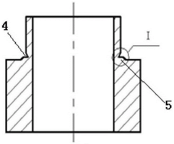
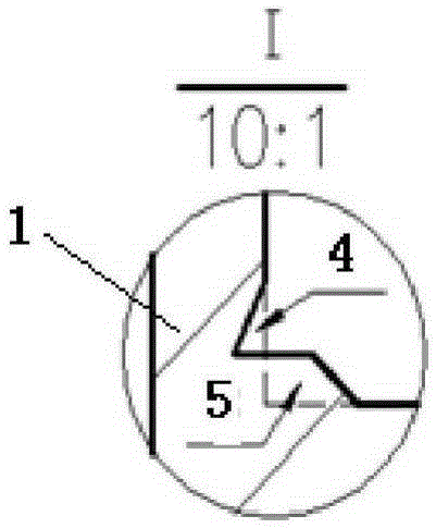
[0026] like figure 2 and image 3 As shown, the copper pad in an embodiment of the present invention is formed by vertically connecting two cylinders, and the diameter of the upper cylinder is smaller than the diameter of the lower cylinder; the connection between the upper cylinder and the lower cylinder is provided with a groove 4 The bottom end of the groove 4 is connected to the upper bottom surface of the lower cylinder through the boss 5, and the boss 5 includes a horizontal part connected to the bottom end of the groove 4, and the horizontal part is connected to the bottom of the groove through an inclined part. The upper bottom surface of the lower cylinder is connected, and the angle between the horizontal part and the inclined part is greater than or equal to 90°.

[0027] like Figure 8 As shown, the middle part of the copper plate of the present invention is provided with an installation hole 7 whose size matches the outer diameter of the above-mentioned upper c...


PUM


Abstract

The invention discloses a busbar electric conduction connecting terminal. A copper mat is formed by vertically connecting two cylinders, and the diameter of the cylinder on the upper portion is smaller than the diameter of the cylinder on the lower portion; a groove is formed in the position where the cylinder on the upper portion is connected with the cylinder on the lower portion; installation holes matched with the outer diameter of the cylinder on the upper portion in size is formed in the middle of a copper plate, and a protrusion matched with the groove in shape and size is arranged on the lateral wall of the installation hole. According to the busbar electric conduction connecting terminal, after one end of the copper plate is extruded to be deformed, the copper plate can be extruded into the groove to achieve the retreat-stopping effect, rebounding after riveting is accordingly and effectively avoided, and then reduction, caused by rebounding of riveting, of the contact pressure Fn among a copper ring, the copper mat and the copper plate can be effectively avoided. Meanwhile, the contact area between the copper mat and the copper plate is increased, rotation can be effectively avoided, the risks of swelling looseness during pressing heating are effectively reduced, and the electric conductivity is strengthened.

Description

technical field [0001] The invention relates to a bus bar product, in particular to a bus bar conductive connection terminal. Background technique [0002] The busbar conductive connection terminal is the connection structure between the busbar product and other electrical components. When in use, the busbar conductive connection terminal and the other electrical component terminal are fastened by bolts. Most of the busbar products have a positive pole or a negative pole. or a plurality of busbar conductive connection terminals (the various parts of the terminal are connected by riveting), the busbar conductive connection terminal relies on the interference fit between the copper ring and the copper pad to generate static friction to ensure that the copper ring, copper pad and its corresponding riveted copper plate Close contact. [0003] Busbars are usually used for high-power devices. Each connection terminal needs to carry a large current. It is required that each connec...

Claims


Application Information

Patent Timeline
Patent Type & Authority Patents(China)
IPC IPC(8): H01R13/02
Inventor 阳飞邵国平
Owner ZHUZHOU CSR TIMES ELECTRIC CO LTD
Why Eureka
Try Eureka