Connector for flexible placode
A technology of flexible substrates and connectors, applied in the direction of connection, contact parts, electrical components, etc., can solve the problems of increased price of flexible substrates, complex structure, miniaturization restrictions, etc., to avoid insufficient resin filling and stabilize contact performance , the effect of improving reliability
- Summary
- Abstract
- Description
- Claims
- Application Information
AI Technical Summary
Problems solved by technology
Method used
Image

Examples
Embodiment 1
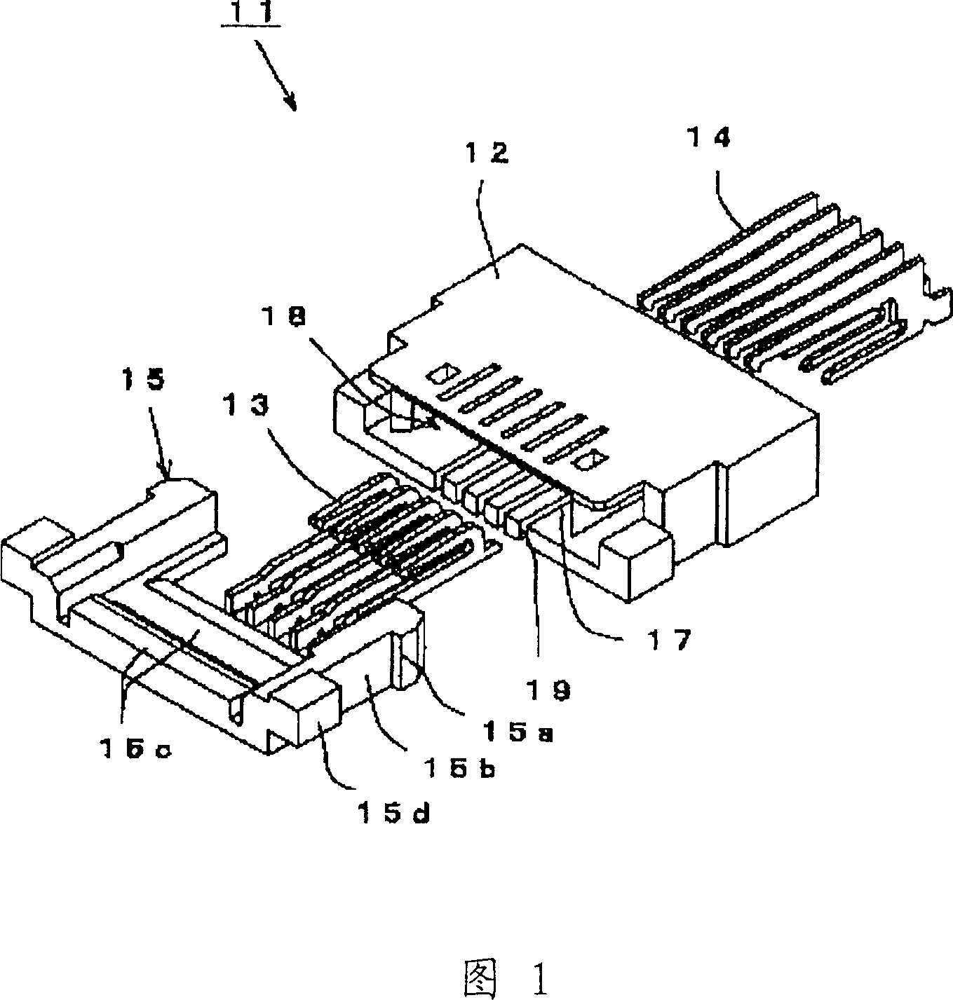
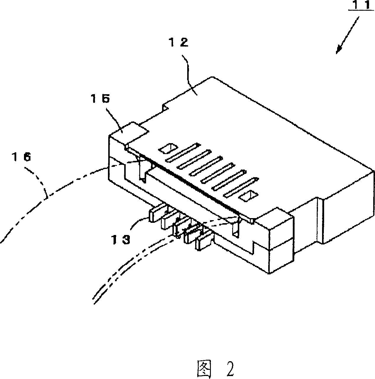
[0067] FIGS. 1 and 2 show a connector 11 for a flexible substrate including a housing 12 , a front connector 13 , a rear connector 14 , and a slider 15 .
[0068] The housing 12 used here is formed into a flat plate using a resin material suitable for insulation, and has an installation port 17 opened horizontally in the front of the housing 12, which is used to connect the flexible substrate 16; 17 communicates with a cavity 18 for connecting a flexible substrate.
[0069] In addition, on the front side of the housing 12 communicating with the mounting port 17 and the hollow portion 18, front press-fit grooves 19 are formed side by side at regular intervals in the left-right direction of the housing 12, which are used to respectively press-fit and fix the front. Linker 13.
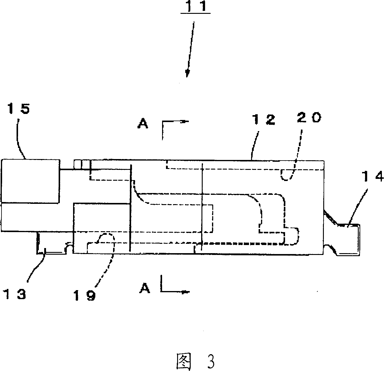
[0070] Further, on the rear side of the case 12, as shown in FIG. 3, rear press-fit grooves 20 are formed side by side at regular intervals in the left-right direction of the case 12, and are used to pre...
Embodiment 2
[0083] As shown in FIG. 10 and FIG. 11 , the difference between the flexible substrate connector 101 of the second embodiment and the flexible substrate connector 11 of the first embodiment is that the pressing direction of the rear connector 104 is from The upper direction of the housing 102 is pressed down and the heights of the upper contact parts 103a, 104a of the front and rear connectors 103, 104 are consistent at the same height. Even if the housing 102 and the slider 105 have different shapes, they have the same function and can obtain the same effect, so only the differences are described.
[0084] The top press-in groove 106 of the above-mentioned housing 102 is arranged side by side on the upper rear side of the housing 102 in the left-right direction, wherein the long L-shaped rear connector 104 is pressed in and installed in a flat state.
[0085] In this case, as shown in FIGS. 12 and 13 , an upper contact portion 104 a is arranged on the L-shaped inner end of th...
Embodiment 3
[0093] As shown in FIG. 14 and FIG. 15 , the difference between the flexible printed circuit connector 141 of the third embodiment and the flexible printed circuit connector 11 of the first embodiment is that the pressing direction of the front connector 143 is from The bottom of the housing 142 is pressed upward. The housing 142 and the slider 145 have different shapes but have the same function and can obtain the same effect, so only the differences will be described.
[0094] The lower pressing groove 146 of the above-mentioned housing 142 is arranged side by side on the lower front side of the housing 142 in the left-right direction, and the long J-shaped front connector 143 is press-fitted from below in a flat state and installed.
[0095] In this case, as shown in FIGS. 16 and 17 , an upper contact portion 143 a is provided at the J-shaped inner end of the front connector 143 , and the upper contact portion 143 a is interposed above the hollow portion 148 inside the housi...
PUM
 Abstract
Description
Claims
Application Information
 - R&D
- Intellectual Property
- Life Sciences
- Materials
- Tech Scout
- Unparalleled Data Quality
- Higher Quality Content
- 60% Fewer Hallucinations
Browse by: Latest US Patents, China's latest patents, Technical Efficacy Thesaurus, Application Domain, Technology Topic, Popular Technical Reports.
© 2025 PatSnap. All rights reserved.Legal|Privacy policy|Modern Slavery Act Transparency Statement|Sitemap|About US| Contact US: help@patsnap.com