
Method and device for automatically planting optical fiber into composite materials based on fiber laying and placing

A composite material and fiber laying technology, which is applied in the direction of measuring the changing force of the optical properties of the material when it is stressed, can solve the problem of inability to meet the requirements of large-scale high-precision production, low optical fiber positioning accuracy, and low implantation efficiency. and other problems, to achieve the effect of preventing torsional deformation, improving manufacturing accuracy and quality, and improving survival rate

Inactive Publication Date: 2014-05-14
XI AN JIAOTONG UNIV +1
View PDF5 Cites 7 Cited by
  • Summary
  • Abstract
  • Description
  • Claims
  • Application Information

AI Technical Summary

Problems solved by technology

The method of manually implanting optical fibers is time-consuming and laborious. It is necessary to measure the corresponding size to determine the implantation position of the optical fiber, and it is necessary to manually fix the optical fiber at the implantation position. The implantation efficiency is low. At the same time, the positioning accuracy of the optical fiber is relatively low, which cannot meet Requirements for large-scale and high-precision production in batches

Method used


Image

  • Method and device for automatically planting optical fiber into composite materials based on fiber laying and placing
  • Method and device for automatically planting optical fiber into composite materials based on fiber laying and placing
  • Method and device for automatically planting optical fiber into composite materials based on fiber laying and placing

Examples


Embodiment Construction

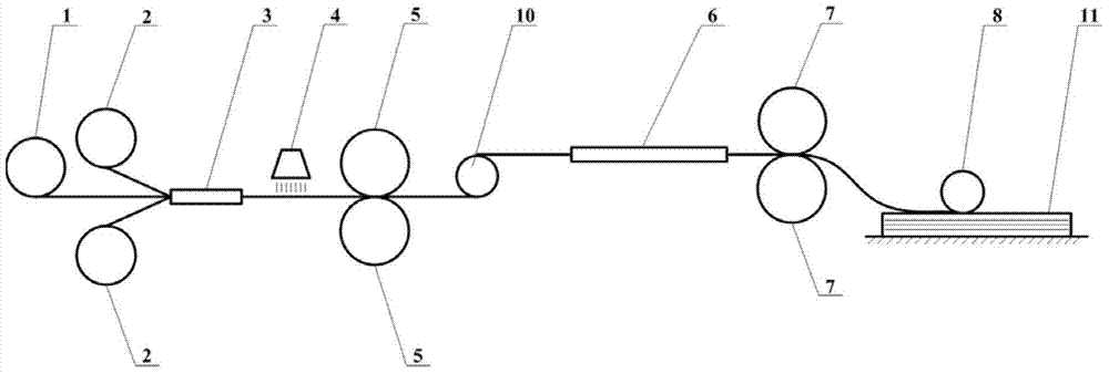
[0027] The present invention will be described in further detail below in conjunction with the accompanying drawings.

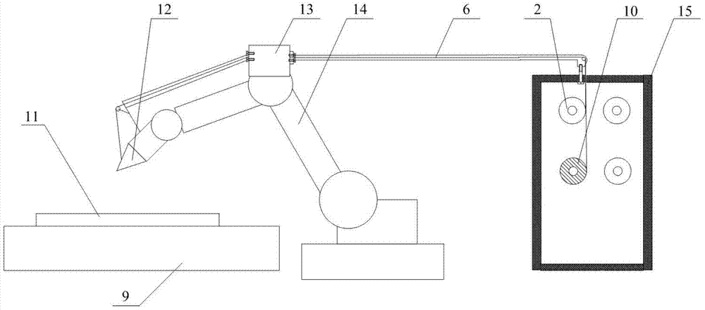
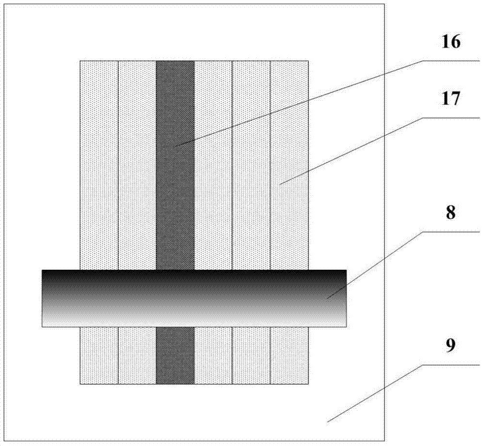
[0028] refer to Figure 1 to Figure 4 A method for automatically implanting an optical fiber into a composite material based on fiber laying provided by the present invention comprises the following steps:

[0029] 1) Place the optical fiber winding roll 1 wound by the optical fiber 18 between two single-layer prepreg tape rolls 2, so that the optical fiber 18 and the single-layer prepreg tape 17 are driven by the flexible pressure roller 5 through the conveying channel 3 directions Front conveying, in which the conveying channel 3 plays the role of constraining and positioning the optical fiber 18 and the single-layer prepreg tape 17; then it is heated by the infrared lamp heating device 4, and the heating temperature is 40-50°C. Since the surface of the single-layer prepreg tape 17 is coated Covered with resin, the viscosity of the resin is increased by th...


PUM


Abstract

The invention discloses a method and device for automatically planting optical fiber into composite materials based on fiber laying and placing. The device comprises a manipulator used for laying and placing single-layer prepreg tape and double-layer prepreg tape with the middle wrapped by the optical fiber, a laying and placing head is arranged at the front end of the manipulator, and a prepreg tape conveying channel used for conveying prepreg is arranged on the manipulator. In the laying and placing process, the optical fiber to be planted in is placed between two pieces of single-layer prepreg tape, and the optical fiber is wrapped in the double-layer prepreg tape so as to effectively improve the survival rate for planting the optical fiber into the composite materials. The automatic panting-in technology is adopted in the process for planting the optical fiber into the composite materials, the single-layer prepreg tape is laid and placed on a substrate to a required thickness by the laying and placing head, then the double-layer prepreg tape with the middle wrapped in optical fiber is laid and placed at the required position, then the single-layer prepreg tape is laid and placed a required thickness continuously, and namely the intelligent composite materials can be obtained. With the method, the optical fiber can be effectively prevented from twisting and shifting in the conveying process, and therefore the positioning accuracy for planting the optical fiber into the composite materials is not affected, and the planting-in efficiency and quality of the optical fiber can be improved.

Description

technical field [0001] The invention relates to the field of optical fiber intelligent composite material manufacturing, and relates to a prepreg-tape-protected optical fiber automatic implantation method and device, in particular to a fiber laying-based automatic optical fiber implantation composite material method and device. Background technique [0002] Optical fiber intelligent composite material is a kind of intelligent composite material that has been studied more at home and abroad at present. The simple intelligent composite material is formed by embedding optical fiber sensors in the composite material. When the composite material plate is subjected to external force, the composite material plate will be deformed, and the fiber optic sensor embedded in the composite material will be deformed accordingly, causing changes in the fiber optic signal. These signal changes directly reflect the internal state of the material. By processing the signal, the damage and strai...

Claims


Application Information

Patent Timeline
IPC IPC(8): G01L1/24
Inventor 段玉岗李金键王奔高侃
Owner XI AN JIAOTONG UNIV
Learn More