Eureka AIR delivers breakthrough ideas for toughest innovation challenges, trusted by R&D personnel around the world.

Portable and quick-open type high-pressure stop valve

A quick-opening, shut-off valve technology, applied in the direction of lift valves, valve devices, engine components, etc., can solve the problems of longer opening and closing time of the shut-off valve, large opening and closing, and large diameter of the valve stem, so as to shorten the opening time , reduce the opening force, reduce the effect of spring preload

Inactive Publication Date: 2014-05-14
BEIJING UNIV OF TECH
View PDF4 Cites 11 Cited by
  • Summary
  • Abstract
  • Description
  • Claims
  • Application Information

AI Technical Summary

Problems solved by technology

However, as globe valves continue to be used in high-pressure environments, their defects become more obvious. The most obvious is that due to the high-pressure fluid resistance, the force required for opening and closing is very large, and the diameter of the valve stem must be large, otherwise it will happen. The failure of the top bending of the valve stem; and in order to apply a large thrust to the valve stem when the valve is opened and closed, the current form of movement of the valve stem is mainly the lifting and rotating rod type, which not only makes the processing complicated, but also makes the opening and closing of the globe valve difficult. Closed time becomes longer

Method used


Image

  • Portable and quick-open type high-pressure stop valve
  • Portable and quick-open type high-pressure stop valve
  • Portable and quick-open type high-pressure stop valve

Examples


Embodiment Construction

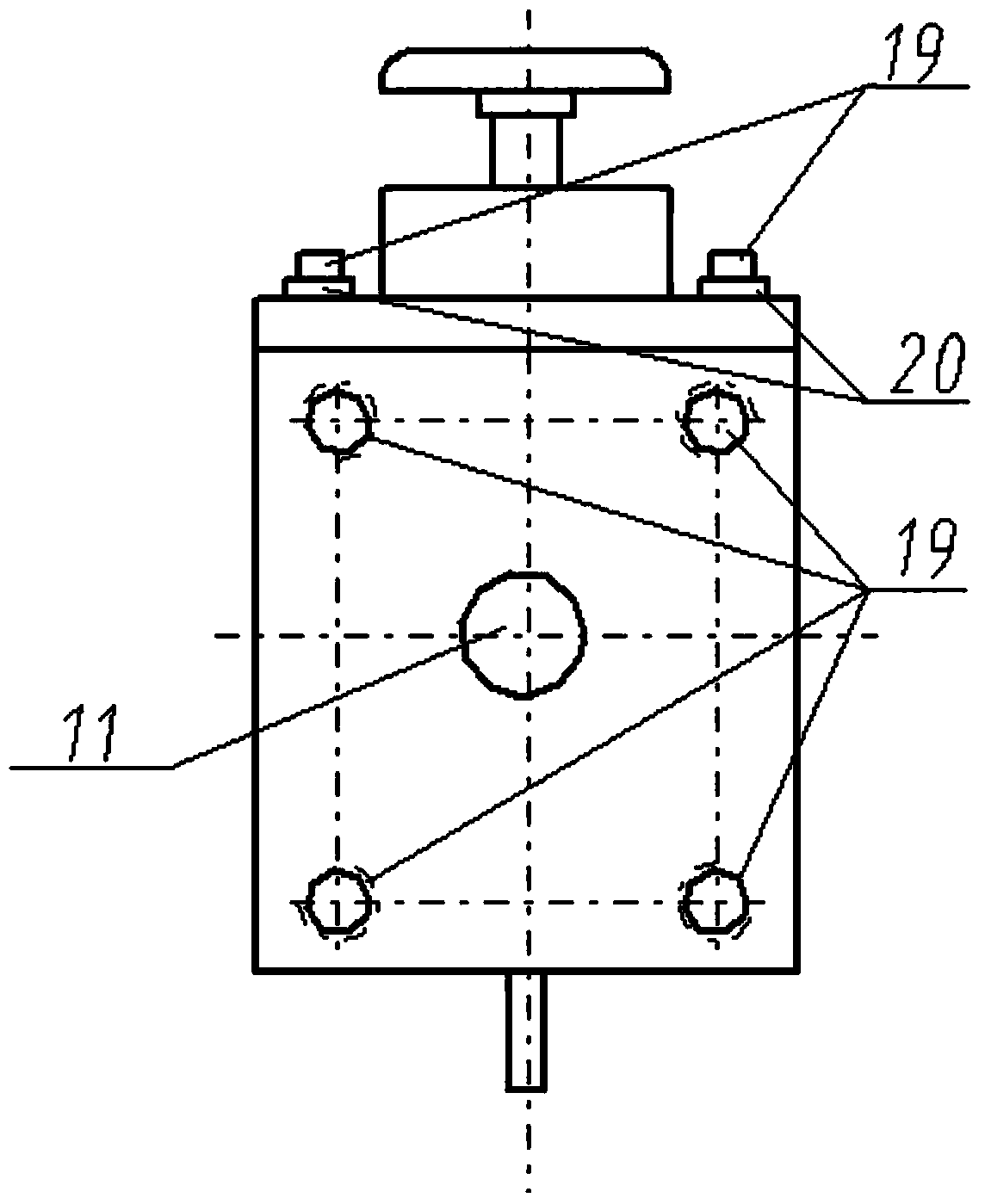
[0030] Turn the adjustment handwheel (18) to move the spool pressure rod (16) up to the predetermined position. At this time, both the main spool spring (14) and the auxiliary spool spring (12) have a certain pretightening force to close the stop valve. , that is, the taper mating surfaces of the main valve core (7) and the main valve port (6) on the valve body (1), the auxiliary valve core (10) and the auxiliary valve port (8) at the lower end of the main valve core (7) are all It plays a sealing role, so that the water inlet and the water outlet are not connected; when the high-pressure liquid enters the stop valve through the water inlet, the solution enters the main valve core (7) through the four flow channel holes uniformly distributed along the circumferential direction of the axis. In the cavity of the spool (7), the upper and lower surfaces of the cavity of the main spool (7) are subject to the same pressure. Push the spool push rod (2) to move up, the auxiliary spool...


PUM


Abstract

The invention relates to a portable and quick-open type high-pressure stop valve and belongs to key hydraulic components for opening and closing of high-pressure hydraulic pipelines. The portable and quick-open type high-pressure stop valve comprises a valve body, a valve spool push bar, a main valve spool, an auxiliary valve spool, an auxiliary valve spool spring, a main valve spool gland, a main valve spool spring, a valve spool pressure bar, a bonnet and an adjusting hand wheel. The main valve spool is disposed in the cavity of the valve body, the main valve spool grand is fixedly connected to the top of the main valve spool, four throughflow holes are evenly formed along the circumferential direction in the side wall of the main valve spool, and a water inlet in the valve body and the cavity inside the main valve spool are communicated through the throughflow holes. A tapered auxiliary valve port is formed in the bottom of the main valve spool, and the valve spoon push bar is of a stepped shaft structure with thin top and thick bottom and sequentially penetrates the valve body and the auxiliary valve port to push the auxiliary valve spool to move axially. A fluid flow channel is arranged in the position of the water outlet of the valve body so that the water outlet is communicated with the cavities formed by the main valve spool grand, the valve spool pressure bar and the valve body. The auxiliary valve spool spring is connected between the main valve spool grand and the auxiliary valve spool. The main valve spool spring is connected between the main valve spool grand and the valve spool pressure bar.

Description

technical field [0001] The invention relates to a portable and quick-opening high-pressure cut-off valve, which belongs to the key element for the opening and closing of high-pressure hydraulic pipelines, and is especially suitable for high-pressure water guns that need to be opened and closed quickly. technical background [0002] The globe valve is the most widely used valve. It is popular because the friction between the sealing surfaces is small during the opening and closing process, it is relatively durable, the opening and closing time is short, it is easy to manufacture, and it is convenient to maintain. Low pressure, but also suitable for high pressure. However, as globe valves continue to be used in high-pressure environments, their defects become more obvious. The most obvious is that due to the high-pressure fluid resistance, the force required for opening and closing is very large, and the diameter of the valve stem must be large, otherwise it will happen. The ...

Claims


Application Information

Patent Timeline
Patent Type & Authority Applications(China)
IPC IPC(8): F16K1/32F16K1/36
CPCF16K1/00F16K1/32F16K1/36F16K1/48
Inventor 聂松林廖伍举张振华张坤生赵俊波张安庆
Owner BEIJING UNIV OF TECH
Why Eureka
Eureka Blog
Learn More