


Quick Research
Generate reliable direction feasibility study reports for your R&D in just a few steps.

Technical Q&A
Discover and master advanced knowledge NOW. Basics, ideas, possibilities, all at once.

Find Solutions
As an expert in R&D theories, this can generate solutions to your technical problems instantly.

Evaluate Feasibility
Analyze your overall solution with one click, know your potential R&D risks in advance.

Monitor Landscape
Get weekly tech updates, stay abreast of the latest tech innovations and key insights.
Mechanical underground sleeve valve
A mechanical, casing valve technology that is applied in wellbore/well valve devices, wellbore/well parts, sealing/packing, etc., and can solve problems such as low reliability, bit scraping of the valve body, easy drilling, etc. problems, to achieve the effect of simple structure, reduced operation difficulty and low production cost
- Summary
- Abstract
- Description
- Claims
- Application Information
AI Technical Summary
Problems solved by technology
Method used
Image

Examples
Embodiment 1
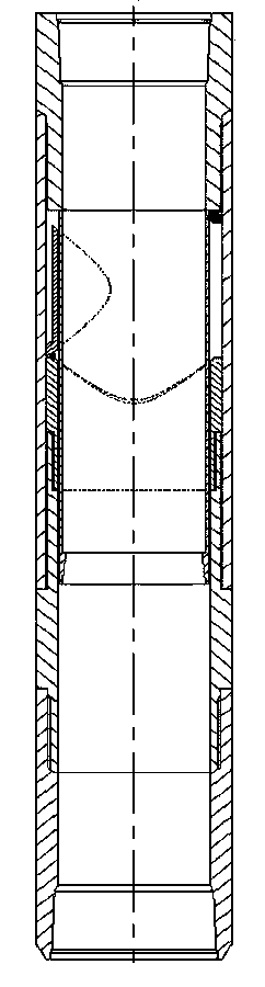
[0042] As a preferred embodiment of the present invention, the present invention discloses a mechanical downhole casing valve, which includes a valve body component, the valve body component includes an upper joint, a valve seat joint, a connecting sleeve, a valve seat and a lower joint, It also includes a protective sliding sleeve and a valve plate for opening and closing the passage in the valve body part. The valve plate is hinged on the valve seat, and the protective sliding sleeve is installed in the valve body part. The inner wall of the joint is matched with the inner wall of the valve seat, and the protective sliding sleeve can slide up and down among the valve body components. The outer wall of the sliding sleeve is provided with a positioning groove that cooperates with the positioning and unlocking.
Embodiment 2
[0044] As another preferred embodiment of the present invention, a funnel-shaped structure with a diameter-reducing step is provided on the upper inner wall of the protective sliding sleeve, and a special tool with a tapered undercut structure is provided in conjunction with the funnel-shaped structure. It is a cylindrical structure, and the extension section of the special tool is an inverted truncated cone structure. The outer diameter of the lower end surface of the inverted truncated cone structure is smaller than the inner diameter of the upper end surface of the protective sliding sleeve, and the outer diameter of the upper end surface of the inverted truncated cone structure is larger than the inner diameter of the protective sliding sleeve. Minimum inner diameter. All the other structures are with embodiment 1.
Embodiment 3
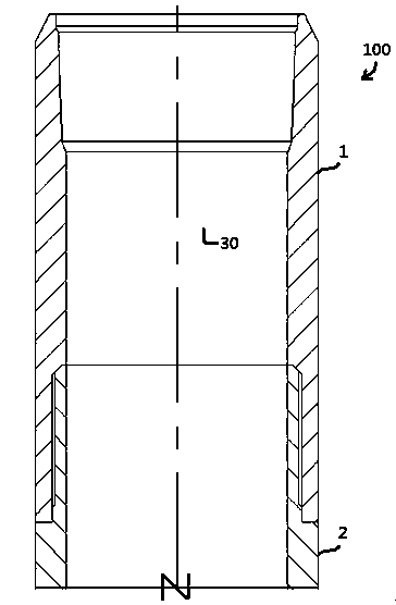
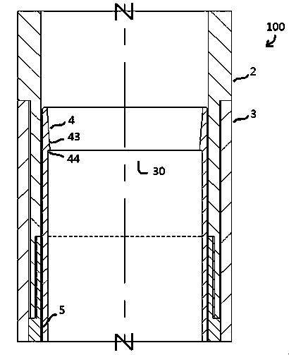
[0046] As yet another preferred embodiment of the present invention, the present invention includes valve body components, which are composed of upper and lower joints, valve seat joints, connecting sleeves, valve seats, valve plates, positioning locks and other components. The upper and lower joints can be connected with the casing through threaded buckles respectively. The lower part of the upper joint is connected with the valve seat joint. The outer thread of the lower part of the valve seat joint is connected with the upper part of the connecting sleeve. The hinge is connected with the core part of the valve body, that is, the switch valve plate, and the lower joint is connected with the lower part of the connecting sleeve through external threads. The inner wall of the connecting sleeve is provided with a positioning lock, which can play the role of positioning the switch sliding sleeve. For casing valves that are initially lowered into the well, a protective sliding sle...
PUM
 Abstract
Description
Claims
Application Information
 - R&D Engineer
- R&D Manager
- IP Professional
- Industry Leading Data Capabilities
- Powerful AI technology
- Patent DNA Extraction
Browse by: Latest US Patents, China's latest patents, Technical Efficacy Thesaurus, Application Domain, Technology Topic, Popular Technical Reports.
© 2024 PatSnap. All rights reserved.Legal|Privacy policy|Modern Slavery Act Transparency Statement|Sitemap|About US| Contact US: help@patsnap.com