Cable-loaded crane combined with hydraulic traction and roller travel and its travel method

A cable-mounted crane and traveling mechanism technology, which is used in the erection/assembly of bridges, bridges, buildings, etc., can solve the problems of one-time re-installation, only dismantling, and inconvenient operation, and achieves easy disassembly and assembly, convenient position adjustment, Small footprint effect

Active Publication Date: 2015-12-30
LIUZHOU OVM MASCH CO LTD
View PDF14 Cites 0 Cited by
  • Summary
  • Abstract
  • Description
  • Claims
  • Application Information

AI Technical Summary

Problems solved by technology

[0004] 1. The hoist-type cable-loaded crane adopts the way of hoist towing and walking. In this way, the hoist must be installed on the bridge tower. Since the wire rope from the hoist to the cable-loaded crane is very long, it is necessary to install every interval on the main cable of the suspension bridge. Guide rollers are installed at a certain distance to ensure that there will be no partial load during traction, which makes the construction complicated and inconvenient to operate;
[0005]2. If the hoist-type cable-loaded crane needs to be towed in the opposite direction, the hoist and guide rollers on the opposite bridge tower must be used. This is difficult to achieve when the cranes are operating at the same time, so it is difficult to achieve double cranes
[0007]1. Slow walking speed: the existing fully hydraulic cable-mounted cranes use hydraulic traction jacks, load conversion jacks and guide rail translation jacks to move step by step, so as to realize the function of the cable-mounted cranes walking on the main cable of the suspension bridge; due to the participation There are three types of hydraulic cylinders for the walking actuator, and the three hydraulic cylinders must perform cyclical actions whether they are walking across the cable clamp or not. Therefore, the walking speed of the entire cable crane is relatively slow, and the average walking speed is only 12m / h;
[0008] 2. It can only be pulled in one direction: once the existing fully hydraulic cable-mounted crane is installed on the main cable of the suspension bridge, it can only be pulled in one direction. If it is to be pulled in the opposite direction, the entire cable-mounted crane To reinstall once;
[0009]3. The installation positions of the legs of the main body of the traveling mechanism of the existing full-hydraulic cable-loaded crane and the legs of the walking guide rail are fixed. If the main body of the entire suspension bridge If there is a discrepancy between the layout of the cable clamps and the actual ones or when temporary clamps are installed, there may be interference, that is, the hoisting feet of the cable-carried crane ride on the clamps. At this time, only the temporary clamps can be removed or the permanent cables can be moved. clip, this is very troublesome;
[0011]5. The steel truss sections of the existing fully hydraulic cable cranes are connected by friction pairs of high-strength bolts. This kind of connection takes a long time to install. Special tool torque wrench is required;
[0012]6. The existing fully hydraulic cable-mounted crane uses a hydraulic pump station driven by an ordinary motor, so the cable-mounted crane is also equipped with a diesel generator. This takes up both space and energy;
[0013]7. The hydraulic lifting jack of the existing full-hydraulic cable-loaded crane is fixedly connected with the steel truss by bolts. The truss needs to be rotated at a large angle, about 15-20 degrees, so the operators on the crane feel uncomfortable, and the hydraulic pump station must be suspended and installed during the swing.

Method used


Image

  • Cable-loaded crane combined with hydraulic traction and roller travel and its travel method
  • Cable-loaded crane combined with hydraulic traction and roller travel and its travel method
  • Cable-loaded crane combined with hydraulic traction and roller travel and its travel method

Examples


Embodiment 1

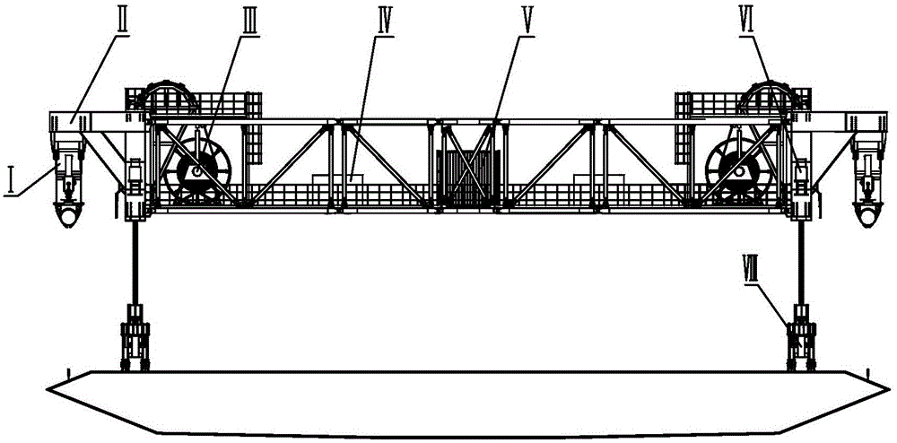
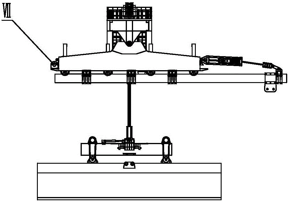
[0072] A cable-loaded crane combined with hydraulic traction and roller travel, such as Figure 1-1~Figure 1-2 As shown, the cable-loaded crane combined with hydraulic traction and roller travel includes traveling mechanism Ⅰ, steel truss Ⅱ, steel strand retracting device Ⅲ, diesel engine hydraulic pump station Ⅳ, control system Ⅴ, lifting jack and cage Ⅵ and hanging Tool Ⅷ; traveling mechanism Ⅰ is installed at both ends of steel truss Ⅱ, steel strand retracting device Ⅲ, diesel engine hydraulic pump station Ⅳ, control system Ⅴ, lifting jack and cage Ⅵ are installed in steel truss Ⅱ, spreader Ⅷ passes through steel truss The twisted wire is connected to the lifting jack;

[0073] As shown in Figure 2-1, the traveling mechanism is composed of four load conversion devices 1, holding feet 2, traveling mechanism main body 3, hoop 4, traction frame 5, traction jack 7 and traction fixing device 8;

[0074] Described load conversion device 1 comprises load conversion jack 11, suppo...

Embodiment 2

[0083] The walking method of the cable-loaded crane combined with hydraulic traction and roller walking. The walking of the cable-loaded crane adopts the combination of hydraulic traction and roller walking. The crane moves from the high point of the main cable to the low point of the main cable. The so-called upward movement means that the cable-loaded crane moves from the low point of the main cable to the high point of the main cable;

[0084] The process of the cable-loaded crane going down is (see Figure 7-1 and Figure 7-2):

[0085] The traction fixing device withstands the cable clamp as a reaction point, the traction frame as a force transmission part, and the hydraulic traction jack provides resistance; when the cable-loaded crane is going to travel, the load conversion jack of the load conversion device lifts the cylinder, and the 4 traveling rollers are all connected to the main Cable contact, the entire cable-loaded crane is jacked up, the upper clamp of the tracti...


PUM


Abstract

A cable-loaded crane combined with hydraulic traction and roller travel, including a traveling mechanism, a steel truss, a steel strand retracting device, a diesel engine hydraulic pump station, a control system, a lifting jack, a cage and a spreader; the traveling mechanism is installed on a steel At both ends of the truss, the steel strand retractable device, diesel engine hydraulic pump station, control system, lifting jack and cage are installed in the steel truss, and the spreader is connected with the lifting jack through the steel strand; the main body of the traveling mechanism is a steel plate The front, rear, left and right symmetrical installation frame, the load conversion device is installed on the main body of the traveling mechanism in a uniform manner, and its rollers are in sliding contact with the main cable; the traction frame is fixedly installed on any end of the main body of the traveling mechanism, and the traction jack and the traction fixing device pass through the traction The frame is connected with the main body of the walking mechanism; the feet are installed at the bottom of the main body of the walking mechanism, and the hoop is installed on the feet. The cable-carried crane adopts the combination of hydraulic traction and roller walking, the walking speed is fast, and the disassembly and assembly of the whole machine is convenient and quick 。

Description

technical field [0001] The invention relates to a bridge construction machine, in particular to a cable-carried crane, which is a bridge erection device for a large suspension bridge. Background technique [0002] Cable-mounted cranes are indispensable equipment in the construction of large-scale suspension bridges. The current cable-mounted cranes include hoist-type cable-mounted cranes and full-hydraulic cable-mounted cranes. They have their own characteristics, but they also have the following shortcomings at: [0003] 1. The deficiencies of the existing hoist-type cable-carried cranes are: [0004] 1. The hoist-type cable-loaded crane adopts the way of hoist towing and walking. In this way, the hoist must be installed on the bridge tower. Since the wire rope from the hoist to the cable-loaded crane is very long, it is necessary to install every interval on the main cable of the suspension bridge. Guide rollers are installed at a certain distance to ensure that there wi...

Claims


Application Information

Patent Timeline
Patent Type & Authority Patents(China)
IPC IPC(8): E01D21/00
Inventor 伍柳毅邓年春刘显晖陈立梁利文李海峰韦富伦甘秋萍严李荣刘俊郭世滔
Owner LIUZHOU OVM MASCH CO LTD
Why Eureka
Try Eureka