Down-moving vapor-liquid flow rope dyeing machine

A rope dyeing machine and steam flow technology, applied in the direction of spray/jet textile material processing, equipment configuration for processing textile materials, etc., can solve the problems of difficulty in ensuring dyeing permeability, inability to dye high-density fabrics, and inability to achieve dyeing effects, etc. , to achieve good dyeing effect, high yield and benefit the environment

Inactive Publication Date: 2015-12-16
HANGZHOU INTELLIGENT DYEING FINISHING EQUIP
View PDF5 Cites 0 Cited by
  • Summary
  • Abstract
  • Description
  • Claims
  • Application Information

AI Technical Summary

Problems solved by technology

It is difficult to popularize because of its own insurmountable defects: (1) because the dyeing method is that the dye solution is sprayed onto the surface of the cloth under the action of airflow, the permeability is poor and it cannot dye high-density fabrics; (2) because its dyeing mainly The air flow acts on the surface of the fabric, so it is difficult to guarantee the dyeing permeability. For particularly heavy fabrics, it is easy to produce quality defects such as color flowering, and the dyeing effect cannot be achieved, and once the dyeing quality problem occurs, it cannot be re-dyeed (repaired); (3) Due to the impact of the steam flow, the light and thin cloth (that is, the weight is less than 60 grams) will be disordered, floating, and irregularly flying during dyeing; (4) Due to the needs of the gas flow, its power consumption is higher than the existing The power consumption of the liquid flow dyeing machine is more than double; (5) Due to the structure of the equipment (the height of the fabric is large), the tension is high during the dyeing cycle, which is easy to produce quality defects; Dyeing of high density and light (less than 60g), heavy cloth

Method used


Image

  • Down-moving vapor-liquid flow rope dyeing machine

Examples


Embodiment Construction

[0013] The technical solutions of the present invention will be further specifically described below through specific embodiments and in conjunction with the accompanying drawings.

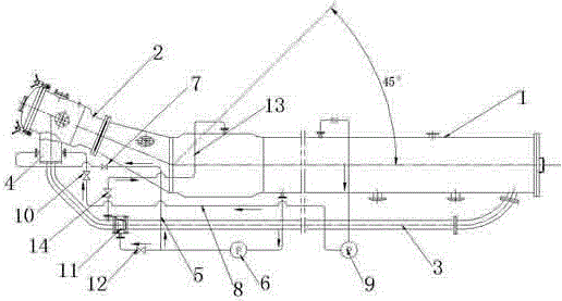
[0014] Such as figure 1 As shown, a downward-moving vapor-liquid flow rope dyeing machine includes a main cylinder body 1, a cloth guide head 2, and a cloth guide pipe 3. The cloth guide head is arranged at the front end of the main cylinder body, and the cloth guide pipe is arranged at the main cylinder body Below, the connection between the cloth guide pipe and the cloth guide head is provided with a steam flow nozzle 4, and a plurality of mist nozzles are arranged in the steam flow nozzle. At the mist nozzle at the steam nozzle device before the pipe layout, the first liquid flow control valve 7 is provided on the liquid flow pipeline; the steam flow pipeline 8 and the steam flow fan 9 are connected to the main cylinder above the main cylinder The steam in the cylinder is extracted to the stea...


PUM


Abstract

The invention discloses a downward-moving type vapor-liquid flow rope dyeing machine which comprises a main cylinder, a cloth guiding head and a cloth guiding pipe. A plurality of vapor-flow nozzles are arranged at the joint of the cloth guiding head and the cloth guiding pipe, a plurality of vapor-flow nozzles are disposed inside the vapor-flow nozzles, a liquid-flow pipeline and a liquid inlet pump which are arranged under the main cylinder are connected to positions of the vapor-flow nozzles in front of the cloth guiding pipe, and a first liquid-flow control valve is arranged on the liquid-flow pipeline; a vapor-flow pipeline and a vapor-flow fan which are connected above the main cylinder extract vapor inside the main cylinder to the position of a vapor-flow nozzle device, and a vapor-flow control valve is arranged on the vapor-flow pipeline; a plurality of liquid-flow nozzles are arranged on the cloth guiding pipe, the liquid-flow pipe and the liquid inlet pump which are arranged under the main cylinder are connected to positions of the liquid-flow nozzles, and a second liquid-flow control valve is arranged on the liquid-flow pipeline; a vapor-flow return pipeline is arranged under the cloth guiding pipe between the vapor-flow nozzles and the liquid-flow nozzles, and a vapor-flow return control valve is arranged on the vapor-flow return pipeline. The downward-moving type vapor-liquid flow rope dyeing machine has the advantages that low liquor ratio of a vapor-flow dyeing machine is kept, and auxiliary dyeing and circulatory conveying of the liquid-flow dyeing machine are sustained.

Description

technical field [0001] The invention relates to a mechanical equipment for dyeing cloth, in particular to a down-moving vapor-liquid flow rope dyeing machine used under high temperature and high pressure, normal temperature and pressure. Background technique [0002] At present, the high-temperature, high-pressure, normal-temperature and normal-pressure liquid flow dyeing machines on the market use the circulating water of the dye liquor to form a dye liquor flow, and under the action of the liquid flow, the cloth is repeatedly cycled to complete the dyeing. A single dyeing and recycling method restricts the efficiency and effect of dyeing, and also limits the space for further reduction of bath ratio, energy consumption and emission reduction. [0003] At present, the high-temperature, high-pressure, normal-temperature and normal-pressure airflow dyeing machines on the market are O-type, which atomize the dye solution under the action of high-speed airflow and spray it circ...

Claims


Application Information

Patent Timeline
Patent Type & Authority Patents(China)
IPC IPC(8): D06B1/02D06B23/20
Inventor 李波
Owner HANGZHOU INTELLIGENT DYEING FINISHING EQUIP
Why Eureka
Try Eureka