Parallel micromanipulation robot

A micro-manipulation and robot technology, applied in manipulators, program-controlled manipulators, manufacturing tools, etc., can solve the problems of less freedom of operation, low motion resolution, and small operating range, so as to improve operating performance, high motion resolution, The effect of a large operating range

Inactive Publication Date: 2014-05-14
TIANJIN UNIVERSITY OF TECHNOLOGY
View PDF9 Cites 3 Cited by
  • Summary
  • Abstract
  • Description
  • Claims
  • Application Information

AI Technical Summary

Problems solved by technology

At present, the main problems of most micro-manipulation robots are complex structure, less freedom of operation, small operation range, and low motion resolution.

Method used


Image

  • Parallel micromanipulation robot
  • Parallel micromanipulation robot
  • Parallel micromanipulation robot

Examples


Embodiment Construction

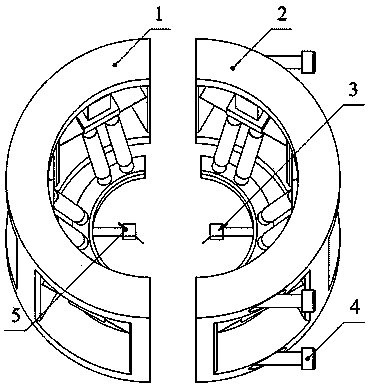
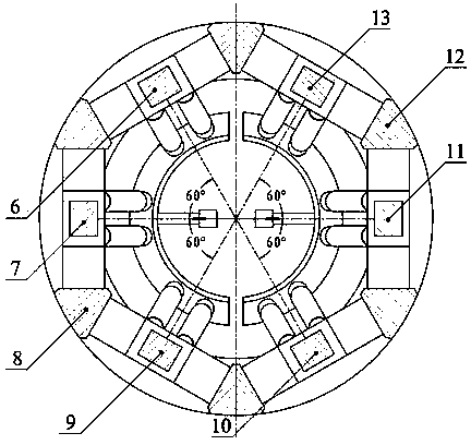
[0019] like figure 1 and figure 2 The parallel micro-manipulation robot shown includes a left micro-manipulator 1 and a right micro-manipulator 2 with the same structure and arranged symmetrically. The left micromanipulator includes a semi-cylindrical left micromanipulator mobile phone holder 8, the first branch chain 6, the second branch chain 7, the third branch chain 9, the left micromanipulator manual platform 18 and the left micromanipulator hand end tool 5. The right micromanipulator includes a semi-cylindrical right micromanipulator mobile phone holder 12, the fourth branch chain 10, the fifth branch chain 11, the sixth branch chain 13, the right micromanipulator manual platform and the right micromanipulator end tool 3.

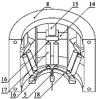
[0020] image 3 In the left micro-manipulator shown, each branch chain includes a micro-displacement driver 15, a flexible moving pair 14 and two branches with the same structure, and each branch is composed of two flexible ball joints 16 and a ri...


PUM


Abstract

A parallel micromanipulation robot comprises a left micromanipulation arm and a right micromanipulation arm, which are the same in structure and symmetrically arranged. Each of the left and right micromanipulation arms comprises a semi-cylindrical micromanipulation arm frame, three branch chains, a micromanipulation arm moving platform and a micromanipulation arm terminal tool. Each branch chain comprises a micro-displacement driver, a flexible prismatic pair and two branches the same in structure; one end of every branch is connected with the left micromanipulation arm moving platform, and the other end of each branch is connected with the corresponding flexible prismatic pair; the axes of the two branches are parallel to each other; the fixed end of the micro-displacement driver is connected with the left micromanipulation arm frame, and the drive end of the micro-displacement driver is connected with the flexible prismatic pair. The three branch chains forming each micromanipulator arm are evenly distributed in a semi-cylindrical space. The parallel micromanipulation robot allows for three-dimensional high-precision operation, is compact in overall structure with wide operating range and high resolution, and is widely applicable to the fields such as biomedical engineering and precision engineering.

Description

technical field [0001] The invention belongs to the field of advanced robots, and in particular relates to a novel parallel micro-operation robot which can be used in biomedical engineering and precision engineering. Background technique [0002] In recent years, science and technology are rapidly developing in the direction of miniaturization, precision, and high integration. Micro-electro-mechanical system processing and assembly, precision surgery, cell manipulation, cell fusion, chromosome cutting, gene injection and other applications require the level of precision and complexity of operations that have far exceeded the limits of human operation. This puts forward an urgent demand for the development of micro-manipulation robots with micro / nano-level positioning accuracy. [0003] Since 1991, countries such as Japan and the United States have begun to invest a lot of funds in the research of micro-manipulation robot systems, and have achieved good results. For exampl...

Claims


Application Information

Patent Timeline
Patent Type & Authority Applications(China)
IPC IPC(8): B25J9/08
Inventor 李杨民肖霄
Owner TIANJIN UNIVERSITY OF TECHNOLOGY
Why Eureka
Try Eureka