
Micromechanical structure

A micro-mechanical structure and micro-mechanical technology, applied in micro-structure technology, micro-structure devices, micro-structure devices composed of deformable elements, etc., can solve problems such as deterioration of sensor resolution, and achieve cost minimization and small dependence. The effect of low sex and space requirements

Active Publication Date: 2014-05-07
ROBERT BOSCH GMBH
View PDF10 Cites 7 Cited by
  • Summary
  • Abstract
  • Description
  • Claims
  • Application Information

AI Technical Summary

Problems solved by technology

Although a centrifugal signal occurs at double the frequency, a correspondingly large dynamic range of the input stage must be maintained in the evaluation circuit in order to avoid overshooting, thereby deteriorating the resolution of the sensor

Method used


Image

  • Micromechanical structure
  • Micromechanical structure
  • Micromechanical structure

Examples


Embodiment Construction

[0016] Identical parts are always provided with the same reference numerals in different figures and are therefore usually also named or mentioned only once in each case.

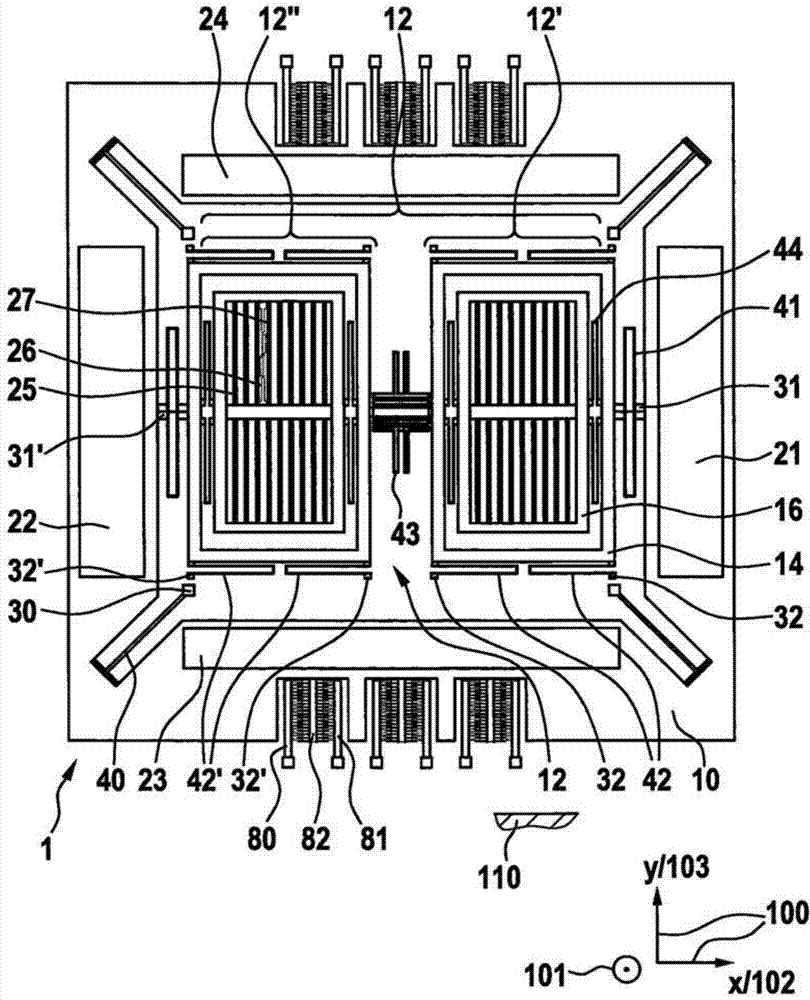
[0017] exist figure 1 A schematic schematic diagram of a micromechanical structure according to the invention, in particular a rotational speed sensor, is shown in . The micromechanical structure is denoted overall with the reference number 1 . The micromechanical structure 1 has a substrate, which is shown only schematically and is designated by reference numeral 110 . The substrate 110 has a main extension plane 100, which in figure 1 is illustrated schematically at the bottom right with the second direction 102 and the third direction 103 and the axis designation x for the second direction 102 and the axis designation y for the third direction 103 . The first direction 101 can be considered to extend perpendicularly to the main extension plane 100 and is also given the designation z. The micromechani...


PUM


Abstract

Micromechanical structure, in particular a yaw rate sensor having a substrate including a main plane of extent for detecting a first yaw rate about a first direction perpendicular to the main plane, a second yaw rate about a second direction parallel to the main plane, and a third yaw rate about a third direction parallel to the main plane and perpendicular to the second direction, includes a rotational oscillating element driven to perform rotational oscillation about a rotational axis parallel to the first direction. The micromechanical structure includes a yaw rate sensor configuration for detecting the first yaw rate that is completely surrounded by the rotational oscillating element in a plane parallel to the main plane. The micromechanical structure includes at least one first connection of the yaw rate sensor configuration on the rotational oscillating element, and at least one second connection of the yaw rate sensor configuration on the substrate.

Description

technical field [0001] The invention proceeds from a micromechanical structure according to the preambles of the independent claims. Background technique [0002] Micromechanical structures or rotational speed sensors are known from the prior art. Such devices have been produced in series production for many years for a variety of applications, for example in the automotive sector and in the consumer electronics sector. The recent multi-axis speed sensor is obviously the most. In the field of consumer electronics this relates in particular to three-axis or three-channel rotational speed sensors or micromechanical structures. In addition to the accuracy and other performance aspects of the micromechanical structure, the small structural size of such micromechanical rotational speed sensors and the associated low costs are also decisive here. It is technically possible here to arrange a three-channel rotational speed sensor (that is to say a rotational speed sensor with thr...

Claims


Application Information

Patent Timeline
Patent Type & Authority Applications(China)
IPC IPC(8): G01C19/5712B81B3/00B81B7/02
CPCG01C19/5712
Inventor J·克拉森R·舍本
Owner ROBERT BOSCH GMBH
Learn More