A Longitudinal Prestressed Strengthening Method of Hollow Slab Girder Bridge
A hollow slab girder and prestressed technology, applied in bridge reinforcement, bridge, bridge maintenance, etc., can solve problems such as large anchor size, potential safety hazards, and difficult anchors, so as to improve longitudinal bearing capacity, prolong service life, The effect of improving shear resistance
- Summary
- Abstract
- Description
- Claims
- Application Information
AI Technical Summary
Problems solved by technology
Method used
Image
Examples
Embodiment 1
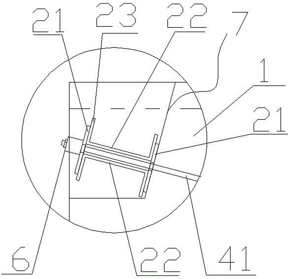
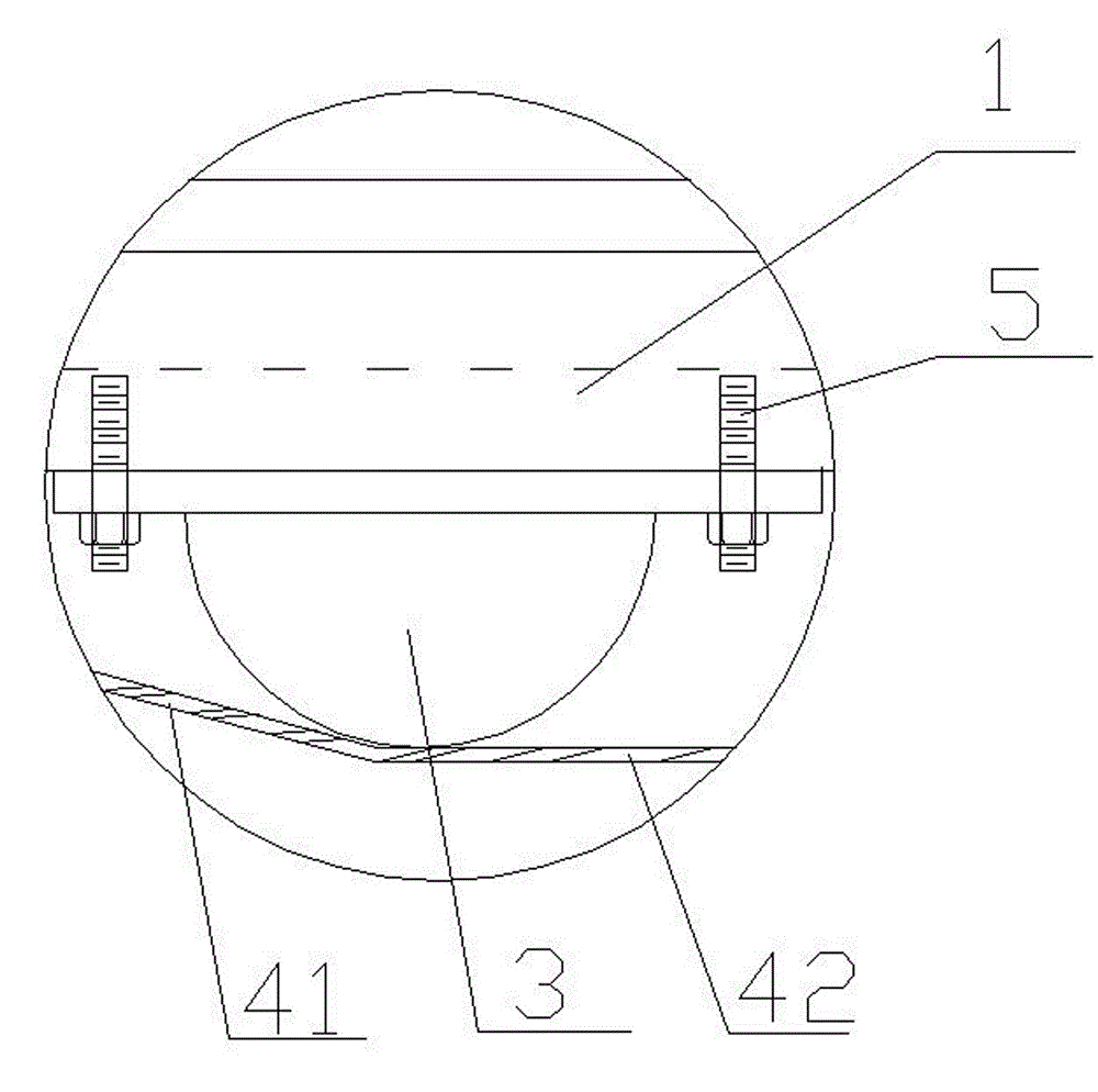
[0022] Embodiment 1: The hollow slab girder bridge in this embodiment is made of conventional hollow slabs, and the broken-line prestressed tendon 4 is selected from a single external steel strand, and the gap between the two channel steels 22 is 2 cm, and the cover plate is connected The diameter of the hole opened at the central position corresponding to the channel steel 22 gap on the 21 is 2 centimeters, and the diameter of the hole punched at the position where the broken line prestressed tendon 4 passes through the hollow slab girder bridge 1 is 2 centimeters. The wires can pass through the above-mentioned gaps between the channel steels, the holes in the connecting plates, and the holes punched on the hollow slab girder bridges. Figure 1 to Figure 4 Shown, a kind of longitudinal prestressed reinforcement method of hollow slab girder bridge of the present invention, carries out successively according to the following steps:
[0023] 1) Design the route of the broken-lin...
Embodiment 2
[0029] Embodiment 2: The difference between this embodiment and Embodiment 1 is that: when the broken-line prestressed tendon 4 in the step 5 is installed, the two ends of the broken-line shaped prestressed tendon 4 are respectively separated from the hollow slab beam bridge in the longitudinal direction. The two diverters 3 below 1 are bypassed, and then the two ends of the broken-line prestressed tendons 4 pass through the hole of the hollow slab girder bridge 1 to the small steel beam 2 respectively, and the broken-line shaped prestressed tendons 4 are placed on the small steel beam. The beam 2 passes through the hole connecting the cover plate 21, the gap between the two channel steels 22, and the hole connecting the cover plate 21, and finally passes the end of the broken line prestressed tendon 4 at the small steel beam 2 through the anchor 6 Anchored after tensioning.
Embodiment 3
[0030]Embodiment three: the difference between this embodiment and embodiment one is that the broken line prestressed tendon 4 is composed of two inclined sections 41 and a horizontal section 42 of prestressed tendons separated from each other, and the step 5 When the broken line prestressed tendon 4 is installed, the two ends of the horizontal section 42 of the broken line shaped prestressed tendon 4 are connected with the diverter 3, and one end of the inclined section 41 of the broken line shaped prestressed tendon 4 is connected with the diverter 3, and then Pass the other end of the inclined section 41 of the broken-line prestressed tendon 4 from the perforated part of the hollow slab girder bridge 1 to the small steel beam 2, and the inclined section 41 of the broken-line shaped prestressed tendon 4 passes through the small steel beam 2 in turn. Go through the hole connecting the cover plate 21, the gap between the two channel steels 22, and the hole connecting the cover ...
PUM
 Abstract
Description
Claims
Application Information
 - R&D
- Intellectual Property
- Life Sciences
- Materials
- Tech Scout
- Unparalleled Data Quality
- Higher Quality Content
- 60% Fewer Hallucinations
Browse by: Latest US Patents, China's latest patents, Technical Efficacy Thesaurus, Application Domain, Technology Topic, Popular Technical Reports.
© 2025 PatSnap. All rights reserved.Legal|Privacy policy|Modern Slavery Act Transparency Statement|Sitemap|About US| Contact US: help@patsnap.com


