
Installation structure and construction method of restraint-typed concrete beam column

A technology for installing structure and concrete, applied in the direction of building structure, construction, etc., can solve the problems of large construction node load, difficulty in pouring and vibrating concrete, enlarged section steel and steel bar, etc., so as to improve the longitudinal bearing capacity and expand the space. Utilization rate, the effect of reducing component size

Pending Publication Date: 2017-09-12
CHINA CONSTR EIGHT ENG DIV CORP LTD
View PDF0 Cites 0 Cited by
  • Summary
  • Abstract
  • Description
  • Claims
  • Application Information

AI Technical Summary

Problems solved by technology

[0002] In recent years, there has been a large amount of super high-rise building construction in China, and structural engineers often use CFST (concrete-filled steel tube) structures for design, but when S-CFST (solid steel tube concrete) components are connected to reinforced concrete beams, the joints are complicated, that is, the connection design of beam-column joints And the construction is difficult, the load at the construction node is large, and deformation is easy to occur, which leads to the need to increase the distribution of section steel and steel bars to increase the load capacity, which further makes concrete pouring and vibration difficult

Method used


Image

  • Installation structure and construction method of restraint-typed concrete beam column
  • Installation structure and construction method of restraint-typed concrete beam column
  • Installation structure and construction method of restraint-typed concrete beam column

Examples


Embodiment Construction

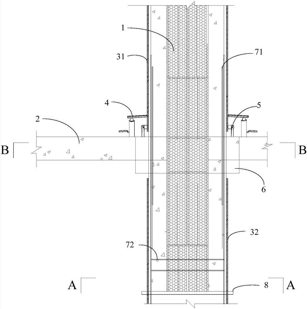
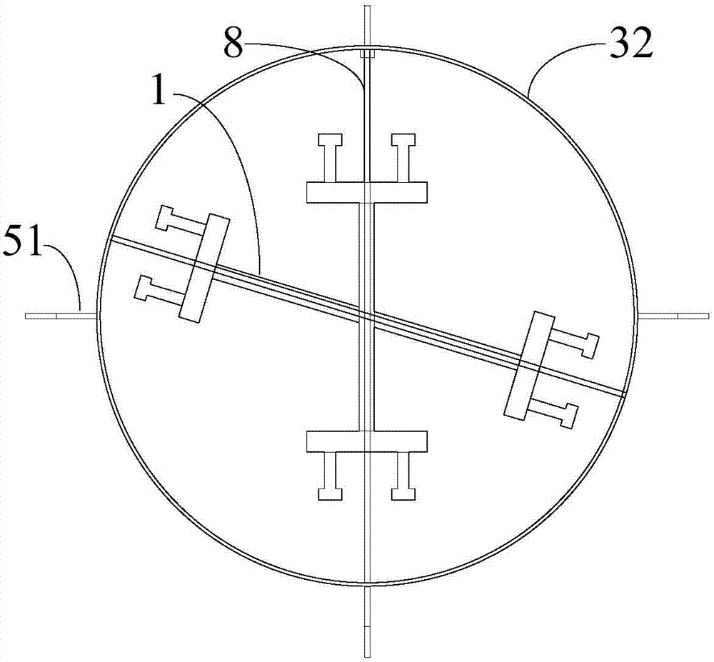
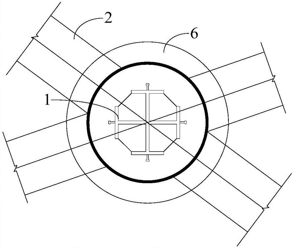
[0034] see figure 1 , figure 2 as well as image 3 The purpose of the present invention is to provide a concrete beam-column installation structure to increase the load and simplify the structure at the joints of the beam-column installation, thereby facilitating concrete pouring and vibration. In order to achieve the above object, the present invention provides a constrained concrete beam column installation structure, including: a prefabricated steel column erected on the foundation structure; a prefabricated steel beam 2 fixed to the prefabricated steel column 1; a constraint Sleeve, the constraint sleeve includes a first cylinder 31 sleeved on the prefabricated steel column 1 above the prefabricated steel beam 2 and a second sleeve sleeved on the prefabricated steel column 1 below the prefabricated steel beam 2 32; and an adjustment support mechanism, including an angle adjustment member 4 for adjusting the angle of the first cylinder body 31 and a reinforcement support...


PUM


Abstract

The invention provides an installation structure and construction method of a restraint-typed concrete beam column. The installation structure comprises a prefabricated steel column vertically arranged on a foundation structure, a prefabricated steel beam fixedly connected with the prefabricated steel column, a restraint sleeve and a adjusting support mechanism, wherein a pouring space for concrete pouring is formed between the restraint sleeve and the prefabricated steel column, and the restraint sleeve comprises a first sleeve body, sleeved above the prefabricated steel beam, of the prefabricated steel column, and a second sleeve body, sleeved below the prefabricated steel beam, of the prefabricated steel column; the adjusting support mechanism includes an angle adjusting piece for angle adjustment of the first sleeve, and a reinforcing support piece which supports between the first sleeve and the prefabricated steel beam. According the installation structure and construction method of a restraint-typed concrete beam column, by segmenting the restraint sleeve into the first sleeve body and the second sleeve body to install, the restraint sleeve does not directly bear the longitudinal load at a beam column point, and only the core part of the prefabricated steel column is restrained; therefore, the longitudinal bearing capacity of the core area of the beam column joint is improved.

Description

technical field [0001] The invention relates to the field of building construction, in particular to a constrained concrete beam column installation structure and a construction method. Background technique [0002] In recent years, there has been a large amount of super high-rise building construction in China, and structural engineers often use CFST (concrete-filled steel tube) structures for design, but when S-CFST (solid steel tube concrete) components are connected to reinforced concrete beams, the joints are complicated, that is, the connection design of beam-column joints And the construction is difficult, the load at the construction node is large, and deformation is easy to occur, which leads to the need to increase the distribution of section steel and reinforcement to increase the load capacity, which further makes concrete pouring and vibration difficult. For this reason, the present invention arises at the historic moment. Contents of the invention [0003] I...

Claims


Application Information

Patent Timeline
IPC IPC(8): E04B1/24E04B1/58
CPCE04B1/24E04B1/2403E04B2001/2406
Inventor 白超傅先珺王昌叶现楼孙元鹏李维强杨秀举林帅赵建伟贺斌
Owner CHINA CONSTR EIGHT ENG DIV CORP LTD
Learn More