Drilling tool wellhead safety protection method

A technology for safety protection and drilling tools, which is applied to drilling equipment, automatic drilling control systems, earthwork drilling and production, etc. It can solve problems such as wasting working time and inability to arrange drilling tool switching, and achieve the effect of improving work efficiency

Active Publication Date: 2016-05-04
CHENGDU ZHUOXIN IND
View PDF9 Cites 0 Cited by
  • Summary
  • Abstract
  • Description
  • Claims
  • Application Information

AI Technical Summary

Problems solved by technology

[0006] In order to overcome the defect that the above-mentioned existing safety device cannot arrange drilling tool switching and other operations after closing the semi-sealed ram blowout preventer, which wastes working time, the present invention provides a drilling tool wellhead safety protection method for the above-mentioned defects. With this method, after the semi-closed ram BOP is closed, the traveling block can still be moved, and operations such as drill tool switching can be performed without wasting working time, improving work efficiency, and preventing the drilling tool from being Pull off, effectively protect the drilling tool

Method used


Image

  • Drilling tool wellhead safety protection method
  • Drilling tool wellhead safety protection method
  • Drilling tool wellhead safety protection method

Examples


Embodiment 1

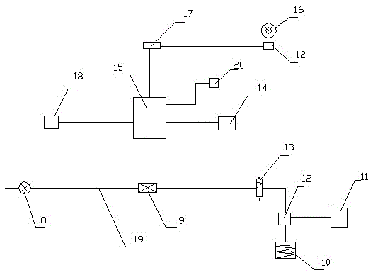
[0041] In this implementation, a hydraulic control valve 8, a normally closed air control device 18, a solenoid valve 9, a normally open air control device 14, a button valve 13 and a tee 12 are sequentially arranged on the air circuit 19 of the brake cylinder of the drilling rig. The air inlet of the three-way 12 is communicated with the button valve 13, and the other two exhaust ports are connected with the brake cylinder 11 of the anti-collision crane, and one is communicated with the brake cylinder 10 of the drilling rig; the button valve 13 is a three-way valve, The two openings are connected to the air circuit 19 of the brake cylinder 10 of the drilling rig, and the other opening is used for exhaust. Just press the button valve 13, and the compressed gas can be discharged from the button valve; the solenoid valve 9 is connected to the control system 15 , the normally open air control device 14, the normally closed air control device 18 and the pressure sensor 17 are all c...

Embodiment 2

[0044] In this embodiment, the difference from Embodiment 1 is that there are two solenoid valves 9, which are connected in parallel to the air circuit 19 of the brake cylinder of the drilling rig. The purpose is that when one of the solenoid valves 9 is damaged, the other solenoid valve is normal. Work without affecting the normal operation of the system, and it is also convenient for workers to replace the solenoid valve.

Embodiment 3

[0046] In this embodiment, the difference from Embodiment 1 is that there are three solenoid valves 9, which are connected in parallel to the air circuit 19 of the brake cylinder of the drilling rig.

[0047] Electromagnetic valve 9 can be multiple, is not limited to one to three, as long as it is connected in parallel on the air circuit 19 of the drilling rig brake cylinder.


PUM


Abstract

The invention relates to a method for safety protection of a drilling tool at a wellhead. According to the method for safety protection of the drilling tool at the wellhead, an electromagnetic valve is arranged on a gas circuit of a brake cylinder of a drilling machine, is in a normally-closed state, and is connected to a control system; a lifting load signal of the drilling tool is collected through a hanging load gauge, the collected lifting load signal is converted into an electric signal through a pressure sensor and then is transmitted to the control system, a critical lifting load is set in the control system, the control system compares the received lifting load signal with the set critical lifting load, the electromagnetic valve is controlled to be opened and the gas circuit is closed when the lifting load is larger than or equal to the critical lifting load, then compressed gas enters the brake cylinder of the drilling machine and a brake cylinder of an anti-collision crown block, and the drilling machine and the anti-collision crown block are stopped. According to the method for safety protection of the drilling tool at the wellhead, after a half-sealed gate blowout preventer is closed, a traveling block can still be moved, work such as replacement of the drilling tool can still be conducted, waste of working hours is avoided, working efficiency is improved, the drilling tool can be prevented from being snapped when the drilling tool is lifted during work, and the drilling tool is effectively protected.

Description

technical field [0001] The invention belongs to the field of petroleum well control, and in particular relates to a method for performing operations such as drilling tool switching without breaking the drilling tool after the semi-sealed ram blowout preventer is closed. Background technique [0002] In the field of oil well control, semi-sealed ram blowout preventers and safety devices are installed at the wellhead. The gas circuit is disconnected through the control valve of the safety device to control the reset of the high and low speed clutch of the drawworks, preventing the pressure regulating valve from entering the air, and the high The low-speed clutch cannot be engaged, and the hook of the traveling block cannot be lifted, thereby achieving the purpose of preventing the drilling tool from being lifted to the half-sealed ram and being hung up. [0003] The authorized announcement number is CN202788794U, and the authorized announcement date is March 13, 2013. The Chin...

Claims


Application Information

Patent Timeline
Patent Type & Authority Patents(China)
IPC IPC(8): E21B44/00B66D5/28F16D65/14F16D121/02F16D125/02
Inventor 陈伦俊罗琼英徐家雄池振华张丽
Owner CHENGDU ZHUOXIN IND
Why Eureka
Try Eureka