A mixing knife assembly

A technology for mixing knives and components, which is applied to mixer accessories, mixers, dissolving, etc., can solve problems such as failure to meet user needs, difficult control of injection molding and embedding process, and failure to meet production needs. Simple and reasonable assembly and structure

Active Publication Date: 2015-11-11
GUANGDONG XINBAO ELECTRICAL APPLIANCES HLDG CO LTD
View PDF5 Cites 0 Cited by
  • Summary
  • Abstract
  • Description
  • Claims
  • Application Information

AI Technical Summary

Problems solved by technology

In the actual production process, the injection molding embedding process is not easy to control, and problems such as stepping on the mold and deformation of the finished product often occur, and the scrap rate is high. Moreover, the mold manufacturing and injection molding process have great restrictions on the shape, quantity and position of the blades, which cannot meet the production needs. , and in the actual use process, the deep hole matched with the positioning shaft of the stirring container causes food residues in it, which makes cleaning difficult and cannot meet the needs of users

Method used


Image

  • A mixing knife assembly
  • A mixing knife assembly
  • A mixing knife assembly

Examples


no. 1 example

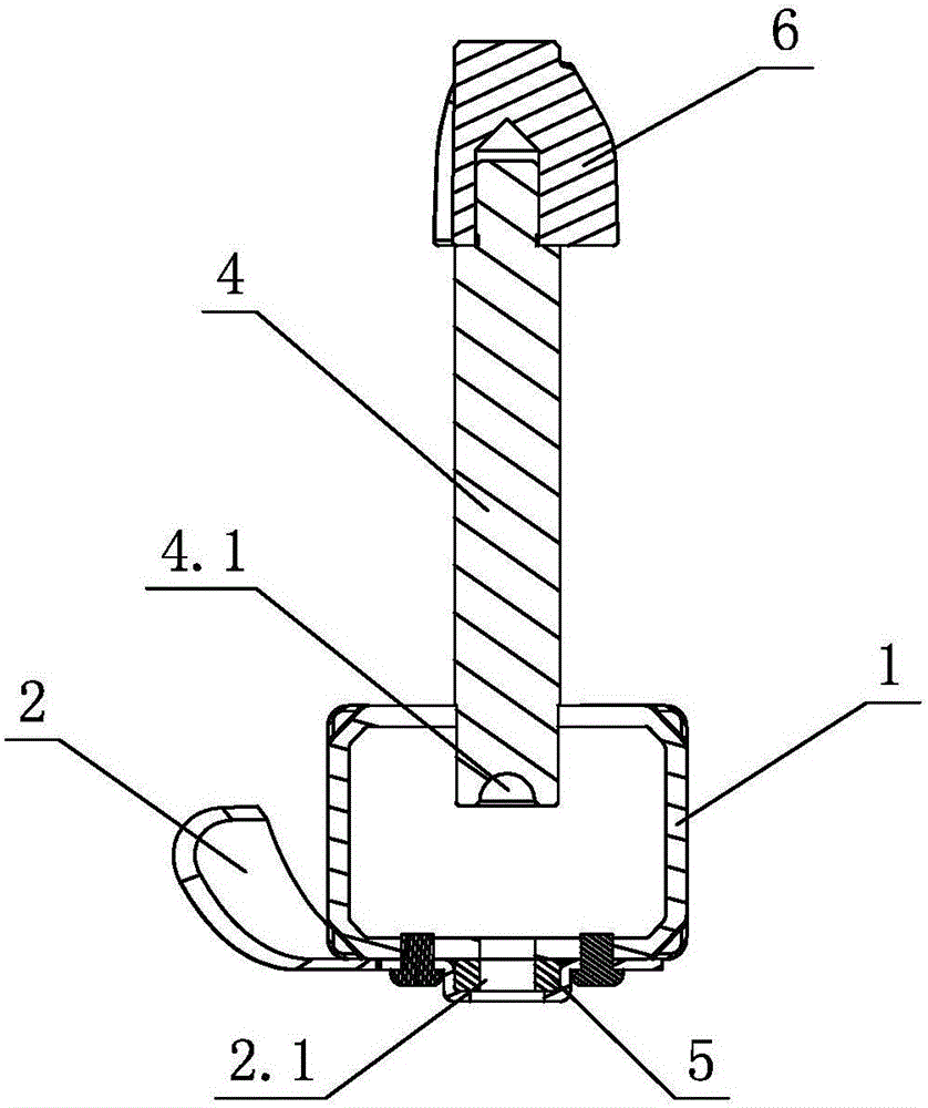
[0018] see figure 1 , figure 2 , This stirring knife assembly at least includes a knife support 1 and a stirring shaft 4, the knife support 1 is a frame structure, and at least one blade is fixed on it; the stirring shaft 4 is fixedly connected with the knife support 1.

[0019] The blade includes a first blade 2 , and the first blade 2 is fixedly arranged at the lower part of the knife holder 1 . The knife support 1 is a frame structure, a cavity 2.1 is provided between the first blade 2 and the knife support 1, and a damping sleeve 5 is provided in the cavity 2.1. The lower part of the stirring shaft 4 is provided with a cavity 4.1, and the upper part thereof is provided with a connector 6 to be connected with the power device of the agitator.

[0020] In order to improve the stirring efficiency, the knife holder 1 is also provided with a knife edge. The knife holder 1 , the stirring shaft 4 and the first blade 2 are arranged on the same axis.

[0021] working principle...

no. 2 example

[0027] see image 3 , Figure 4 , the stirring knife assembly, which is different from the first embodiment is that: the blade includes a first blade 2 and a second blade 3; wherein, the first blade 2 is fixedly arranged in the lower part of the knife support 1, and the second blade 3 is fixedly arranged on the upper part of the knife holder 1.

[0028] Other unmentioned parts are the same as those of the first embodiment.

no. 3 example

[0030] see Figure 5 , Image 6 , the stirring knife assembly, which is different from the first embodiment is that: the blade includes a first blade 2 and a second blade 3; wherein, the first blade 2 is fixedly arranged in the lower part of the knife support 1, and the second blade 3 is fixedly arranged on the stirring shaft 4.

[0031] Other unmentioned parts are the same as those of the first embodiment.


PUM


Abstract

A stirring knife assembly at least comprises a knife bracket and a stirring shaft; the knife bracket is of a framework structure and is fixedly provided with at least one blade; the stirring shaft is fixedly connected with the knife bracket. The lower part of the knife bracket is provided with a first blade, and the upper part of the knife bracket can be provided with a second blade or can be not provided with the blade; the stirring shaft is not provided with a blade or is provided with at least one blade; the mode of blade arrangement on the knife bracket can be combined randomly with the mod of blade arrangement on the stirring shaft. Because the blade is connected with the stirring shaft through a non-injection molding mode, the defects brought by the injection molding process are avoided, the shape and the number of the blades have no limitation, and the blade arranged positions are relatively flexible; and moreover, the blade bracket adopts the framework structure, the braking structure is simplified, at the same time, a deep hole structure, which is matched with a positioning shaft of a stirrer, of a stirring shaft of a traditional stirring knife assembly is avoided, moreover, enough space is left for food to pass through, food is avoided from remaining in the deep hole structure, no cleaning dead angle exist, cleaning becomes easy, and the practicability is high.

Description

technical field [0001] The invention relates to a stirring blade assembly, in particular to a stirring blade assembly applied to a food stirrer. Background technique [0002] In the prior art, the stirring blade assembly of the food stirrer adopts the embedded injection molding process, and the metal blade is used as an insert. Inside the shaft, there is a deep hole structure that matches the positioning shaft of the stirring vessel. In the actual production process, the injection molding and embedding process is not easy to control, and problems such as stepping on the mold and deformation of the finished product often occur. , and in the actual use process, the deep hole matched with the positioning shaft of the stirring container causes food residues in it, which is difficult to clean and cannot meet the needs of users. Therefore, further improvement is necessary. SUMMARY OF THE INVENTION [0003] The purpose of the present invention is to provide a stirring blade as...

Claims


Application Information

Patent Timeline
Patent Type & Authority Patents(China)
IPC IPC(8): B01F15/00
Inventor 郭建刚李智宏
Owner GUANGDONG XINBAO ELECTRICAL APPLIANCES HLDG CO LTD
Why Eureka
Try Eureka