Two-axis planar motion control card and two-axis planar motion control method for fully automatic surface mount system
A motion control card, surface mount technology, applied in the direction of comprehensive factory control, comprehensive factory control, electrical program control, etc., can solve the problems of not being able to reflect the motion state of the controlled device in real time, slow transmission speed of the control card, and low reliability. , to achieve the effect of fast action, high reliability and improved reliability
- Summary
- Abstract
- Description
- Claims
- Application Information
AI Technical Summary
Problems solved by technology
Method used
Image
Examples
specific Embodiment approach 1
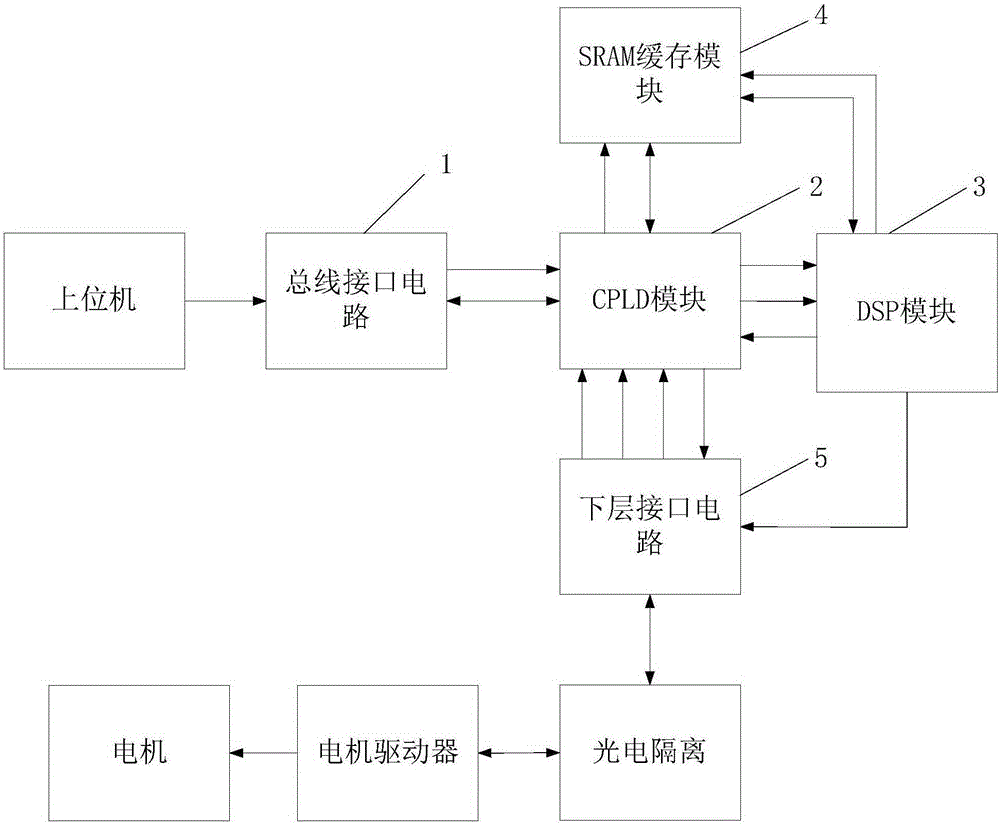
[0030] Specific implementation mode one: refer to figure 1 Specifically illustrate the present embodiment, the two-axis planar motion control card facing the full-automatic surface mount system described in the present embodiment, it includes: bus interface circuit 1, CPLD module 2, DSP module 3, SRAM cache module 4 and lower layer interface Circuit 5;
[0031] The address signal input terminal of the bus interface circuit 1 is connected to the CPLD module 2 address output terminals; the data signal input and output terminals of the bus interface circuit 1 are connected to the data signal output and input terminals of the CPLD module 2;
[0032] The RAM access control signal output end of the SRAM buffer module 4 is connected to the RAM access control signal input end of the CPLD module 2; the RAM data signal input and output ends of the SRAM buffer module 4 are connected to the RAM data signal output and input ends of the CPLD module 2; the SRAM buffer module 4 The SRAM addr...
specific Embodiment approach 2
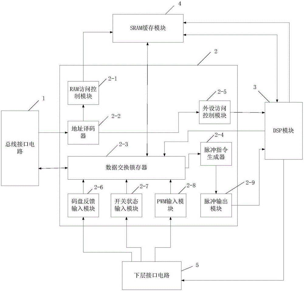
[0038] Specific implementation mode two: refer to figure 1 with figure 2 Describe this embodiment in detail. This embodiment is a further description of the two-axis planar motion control card for a fully automatic surface mount system described in Embodiment 1. In this embodiment,
[0039] CPLD module 2 includes RAM access control module 2-1, address decoder 2-2, data exchange latch 2-3, pulse instruction generator 2-4, peripheral access control module 2-5, code disk feedback input Module 2-6, switch state input module 2-7, PWM input module 2-8 and pulse output module 2-9;
[0040] The RAM access control module 2-1 is used to output the RAM access control signal to the SRAM cache module 4;
[0041] The address decoder 2-2 is used to analyze the address signal of the bus interface circuit 1; the address decoder 2-2 is also used to output the received address signal to the RAM access control module 2-1 and the Peripheral access control module 2-5;
[0042] The data exchang...
specific Embodiment approach 3
[0050] Specific implementation mode three: the two-axis planar motion control method for the fully automatic surface mount system described in this implementation, the specific steps of the method are as follows:
[0051] Step 1, host computer sends control signal to CPLD module 2 through bus interface circuit 1, and the data exchange latch 2-3 of described CPLD module 2 receives this control signal, and this control signal is sent to SRAM cache module 4, SRAM The cache module 4 sends the control signal to the DSP module 3; the DSP module 3 starts a timer interrupt or an external interrupt, if the timer is interrupted, then perform step 2; if it is an external interrupt, then perform step 3;
[0052] Step 2, timer interrupt start, DSP module 3 sends described control signal to the data exchange latch 2-3 of CPLD module 2, and data exchange latch 2-3 sends pulse signal to pulse command generator 2-4, The pulse command generator 2-4 output pulse signal to the pulse output module...
PUM
 Abstract
Description
Claims
Application Information
 - Generate Ideas
- Intellectual Property
- Life Sciences
- Materials
- Tech Scout
- Unparalleled Data Quality
- Higher Quality Content
- 60% Fewer Hallucinations
Browse by: Latest US Patents, China's latest patents, Technical Efficacy Thesaurus, Application Domain, Technology Topic, Popular Technical Reports.
© 2025 PatSnap. All rights reserved.Legal|Privacy policy|Modern Slavery Act Transparency Statement|Sitemap|About US| Contact US: help@patsnap.com


