
A self-locking head structure for screen

A self-locking head and screen technology, applied in optics, instruments, projection devices, etc., can solve the problems of poor self-locking structure stability, high production cost, poor convenience, etc., and achieve strong self-locking stability, low production cost, and structure. unique effect

Active Publication Date: 2016-06-29
蔡兆和
View PDF7 Cites 0 Cited by
  • Summary
  • Abstract
  • Description
  • Claims
  • Application Information

AI Technical Summary

Problems solved by technology

[0005] In order to realize the above-mentioned fast self-locking concept, traditional screen spring screen products are often designed with a manual limit device, that is, the screen is kept fixed after being pulled down by manual mechanical limit. This manual locking method is undoubtedly relatively backward. poor convenience
At the same time, some new screen products are designed into other self-locking forms, such as the self-locking structure in the form of gears, but the principle of this self-locking structure is often too complicated; such as the self-locking structure controlled by the motor, but this The stability of the self-locking structure is poor
The production cost of these new self-locking screen products is usually high, so these self-locking screen products are not ideal choices

Method used


Image

  • A self-locking head structure for screen
  • A self-locking head structure for screen
  • A self-locking head structure for screen

Examples


Embodiment Construction

[0028] The present invention will be described in further detail below according to the drawings and embodiments.

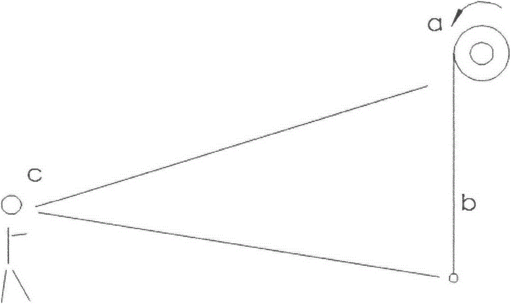
[0029] In order to facilitate the understanding and description of the specific implementation of the present invention, in the pull-down process of the screen, it is generally understood as using such as figure 1 As shown in the more common counterclockwise way of turning a and pulling down the screen b, the demo audience c of the screen is located at figure 1 On the left side of screen b.

[0030] combine figure 2 As shown, when the demo audience c is facing the screen b, a self-locking head structure 100 for the screen according to the present invention is installed at the left end of the screen reel d.

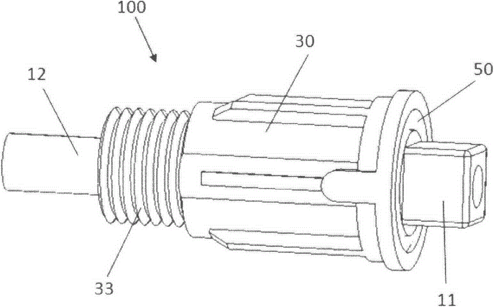
[0031] Such as image 3 , Figure 5 and Figure 7 , Figure 8 , Figure 9 As shown, a self-locking head structure 100 for a screen according to the embodiment of the present invention includes a rotating shaft 10 having a screen connecting portion 11 ...


PUM


Abstract

The invention relates to a self-locking structure for a screen. The self-locking structure comprises a rotating shaft one end of which is provided with a screen connecting part, a steel ball guide rail is fixedly sleeved on the rotating shaft; the steel ball guide rail is provided with a first rail; the first rail comprises a downward pull rail groove formed in the outer surface of the steel ball guide rail and a limit rail groove; the downward pull rail groove is arranged close to the screen connecting part; the rotating shaft is sleeved with a shell in a rotating way; the shell is provided with a cavity capable of movably accommodating the steel ball guide rail; a second rail is concavely arranged on the inner wall of the cavity along the axis direction of the rotating shaft; steel balls are movably mounted on the first rail and the second rail; a first connection part used for fixedly mounting a screen spring is arranged on one end, far away from the screen connecting part, of the shell; the other end of the rotating shaft penetrates through and stretches out of the shell to form a second connecting part. The self-locking structure of the screen is unique in structure, the rapid self-locking is realized under the counter-acting force effect of the screen spring after the screen is pulled down, the self-locking stability is stronger, the convenience and rapidness in use are improved, and the production cost is lower.

Description

technical field [0001] The invention relates to a self-locking head structure for a screen, in particular to a self-locking head structure for realizing rapid self-locking when the screen is pulled down. Background technique [0002] Screens are usually used for teaching demonstrations, movie projections, etc. With the development of society, screens have gradually developed into one of the indispensable office supplies in enterprises. The degree is also getting higher and higher. [0003] In order to meet the convenience of people's daily use, carrying, installation and storage, screen products are usually made in the form of rotatable and shrinkable rolls, which can be pulled down to form a screen when in use. Accidental injury is widely used. For this reason traditional screen products need to use screen spring usually, and screen spring is the main part of screen, is the power device that screen can shrink automatically. [0004] In order to further improve the conven...

Claims


Application Information

Patent Timeline
Patent Type & Authority Patents(China)
IPC IPC(8): G03B21/58
Inventor 蔡兆和
Owner 蔡兆和
Learn More