
Moving target detection method for mimo radar based on non-convex optimization

A technology of moving target detection and non-convex optimization, applied in measuring devices, radio wave measurement systems, radio wave reflection/reradiation, etc., can solve problems such as non-deterministic polynomial difficulties, large gaps, and difficulty in solving sparse solutions

Inactive Publication Date: 2016-07-06
HOHAI UNIV
View PDF4 Cites 0 Cited by
  • Summary
  • Abstract
  • Description
  • Claims
  • Application Information

AI Technical Summary

Problems solved by technology

However, l 0 The optimization problem with norm minimization constraints is a non-deterministic polynomially hard (NP-hard) problem, starting from l 0 Finding sparse solutions in optimization models constrained by norm minimization is quite difficult
[0007] (2) l 1 The optimization problem with norm minimization constraints still cannot guarantee to obtain a satisfactory sparse solution, and it is often inconsistent with the real sparse solution (l 0 solutions to optimization problems with norm minimization constraints) with a large gap
[0008] Therefore, the use of convex optimization algorithms often still cannot obtain more accurate moving target detection results, and the detection results often still have high side lobe levels and low resolution

Method used


Image

  • Moving target detection method for mimo radar based on non-convex optimization
  • Moving target detection method for mimo radar based on non-convex optimization
  • Moving target detection method for mimo radar based on non-convex optimization

Examples


Embodiment 1

[0093] Simulation of detection performance comparison in sparse target scenarios:

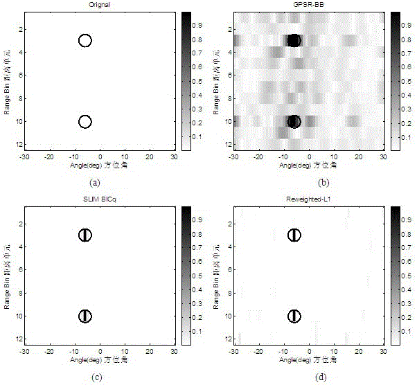
[0094] Assuming that the signal-to-noise ratio is SNR=20dB, two moving targets are set in the observation scene, which are respectively located in the third and tenth distance units. Puler frequency shift, such as figure 2 As shown in (a), the position of the real target is represented by "o" in the imaging map.

[0095]The MIMO radar transmit waveform is the transmit signal waveform designed using the CAN method in the literature [HeHao, StoicaPeti-e, LiJian.DesigningUnimodularSequenceSetsWithGoodCorrelations—IncludinganApplicationtoMIMORadar[J].IEEETransactionsonSignalProcessing,2009,57(11):4391-4405].

[0096] Using the present invention, the GPSR-BB solution algorithm based on the convex optimization problem and the literature [TanXing, RobertsW.T.Jr., LiJian, StoicaPeti-e..SparseLearningviaIterativeMinimizationWithApplicationtoMIMORadarImaging[J].IEEETransactionsonSignalProcessing,2011,5...

Embodiment 2

[0099] Simulation of detection performance comparison in the case of dense targets:

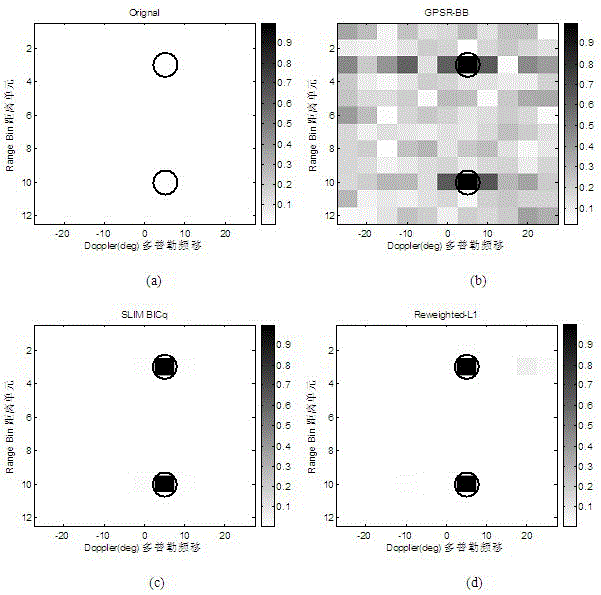
[0100] Under the same experimental parameters and conditions as in Example 1, 24 targets are randomly distributed in the observation scene, all of which have a Doppler frequency shift of 5°, and their positions are distributed as follows Figure 4 Shown in (a). Utilize the present invention, utilize GPSR-BB method and SLIM method to carry out simulation comparison respectively, simulation result is as follows Figure 4 shown. It can be seen that in the case of dense targets, the present invention can accurately detect the position of the target, and the SLIM method can detect most of the target positions, but the GPSR-BB method cannot accurately detect the target.

[0101] In order to verify the Doppler frequency shift resolution of the detection method, when the azimuth angle is 8°, the present invention, the GPSR-BB method and the SLIM method are used to carry out simulation comparisons r...


PUM


Abstract

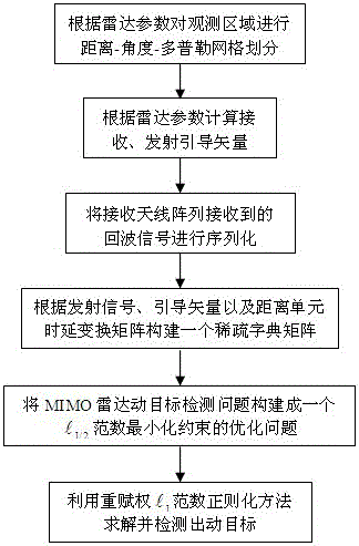
The invention discloses a non-convex optimization based MIMO radar moving object detection method. The method comprises the following steps: according to radar parameters, performing distance-angle-Doppler grid dividing on an observation area; according to radar emission, the position of a receiving array, and radar observation area parameters, calculating emission and reception guiding vectors; according to emission signal waveforms, the guiding vectors and a distance unit time delay transformation matrix, constructing a sparse dictionary matrix; performing serialization on echo signals received by an antenna array; and according to an aforementioned model, constructing MIMO radar moving object detection to be an optimization problem of an L[1 / 2] norm minimizing constraint; and using a heavy weight determining L[1] norm regularization method to solve the optimization problem, obtaining distance-angle-Doppler imaging of a MIMO radar moving object, and detecting a moving object in the observation area. By using the method provided by the invention, a moving object detection result more accurate than a result by use of a convex optimization algorithm can be obtained, and the detection result is higher in resolution.

Description

technical field [0001] The invention relates to a radar moving target detection method, in particular to a non-convex optimization-based MIMO radar moving target detection method. Background technique [0002] In recent years, with the gradual deepening of radar research, a new radar system - Multiple-Input Multiple-Output (MIMO, Multiple-Input Multiple-Output) radar has been introduced in the radar field. MIMO radar is a radar system that uses multiple transmitting antennas to send specific waveform signals, and uses multiple receiving antennas to perform some joint processing on the echoes. The basic idea is to obtain space diversity and virtual aperture respectively through waveform diversity technology to improve the performance of radar detection. Once the radar system was proposed, it attracted widespread attention. A large number of scholars have carried out in-depth research in the fields of target detection, parameter estimation, waveform estimation and target reco...

Claims


Application Information

Patent Timeline
Patent Type & Authority Patents(China)
IPC IPC(8): G01S13/50G01S13/89G01S7/41
CPCG01S7/41G01S13/505G01S13/89
Inventor 鹿浩陈亮王佳希胡晓雯曹宁
Owner HOHAI UNIV
Learn More