
Laser tracking measurement system having spherical revolution bounce error compensation function and compensation method thereof

A technology of laser tracking measurement and spherical surface rotation, which is used in measuring devices, mapping and navigation, and optical devices, etc., can solve the problems of high precision spherical surface rotation, difficult processing and manufacturing, large errors, etc., to reduce the difficulty of processing and manufacturing. Cost, simple structure, and the effect of reducing measurement error

Active Publication Date: 2014-04-23
XI AN JIAOTONG UNIV
View PDF5 Cites 15 Cited by
  • Summary
  • Abstract
  • Description
  • Claims
  • Application Information

AI Technical Summary

Problems solved by technology

However, when the interferometric accuracy is determined during the multilateral measurement process, the spherical gyration runout error of the tracking mechanism that changes the laser beam pointing will introduce a large error into the final distance measurement
In traditional laser tracking measurement equipment, the spherical rotation accuracy of the laser tracking measurement mechanism is highly required, and the processing and manufacturing are difficult and costly.

Method used


Image

  • Laser tracking measurement system having spherical revolution bounce error compensation function and compensation method thereof
  • Laser tracking measurement system having spherical revolution bounce error compensation function and compensation method thereof
  • Laser tracking measurement system having spherical revolution bounce error compensation function and compensation method thereof

Examples


Embodiment Construction

[0032] The present invention will be described in detail below in conjunction with the accompanying drawings.

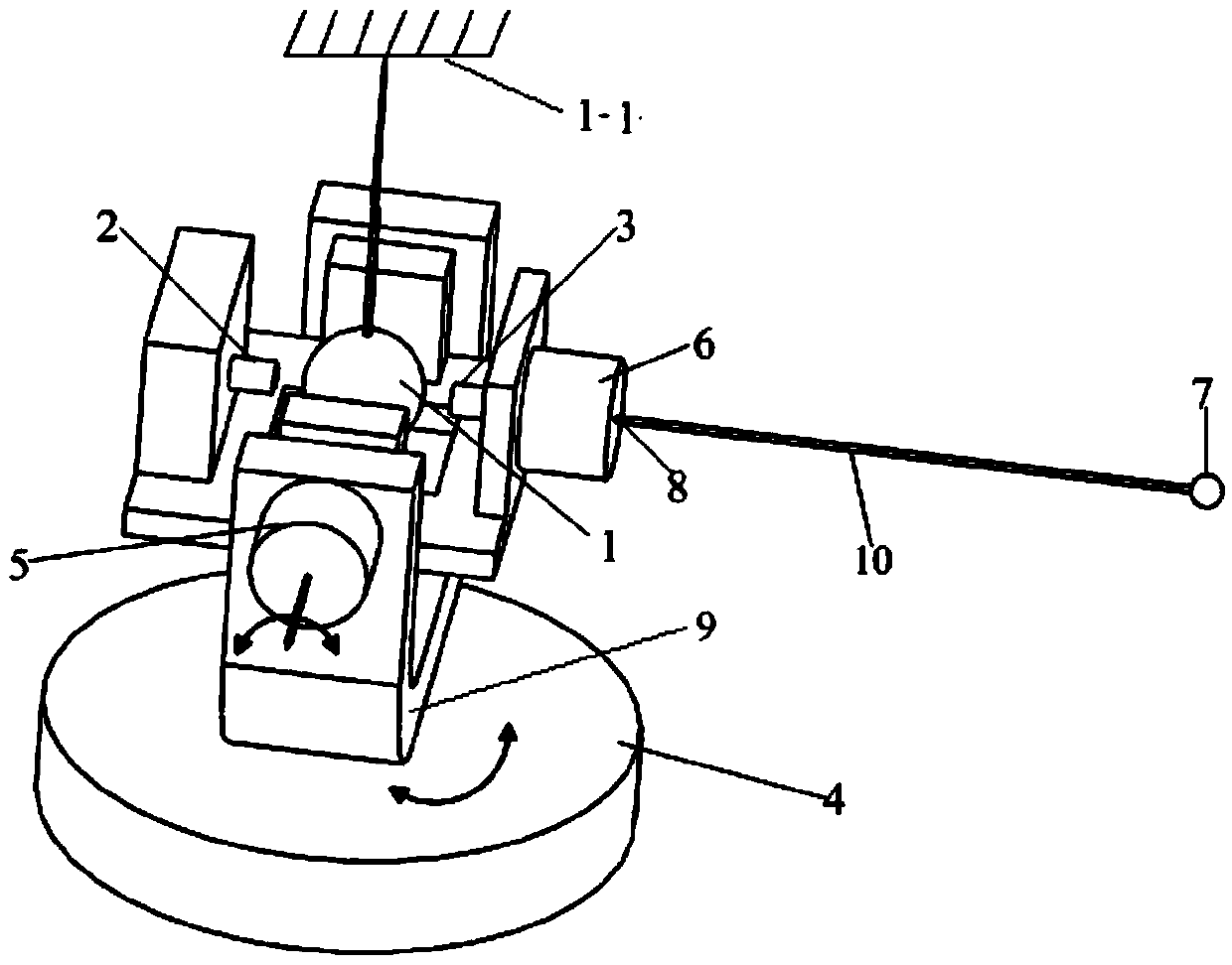
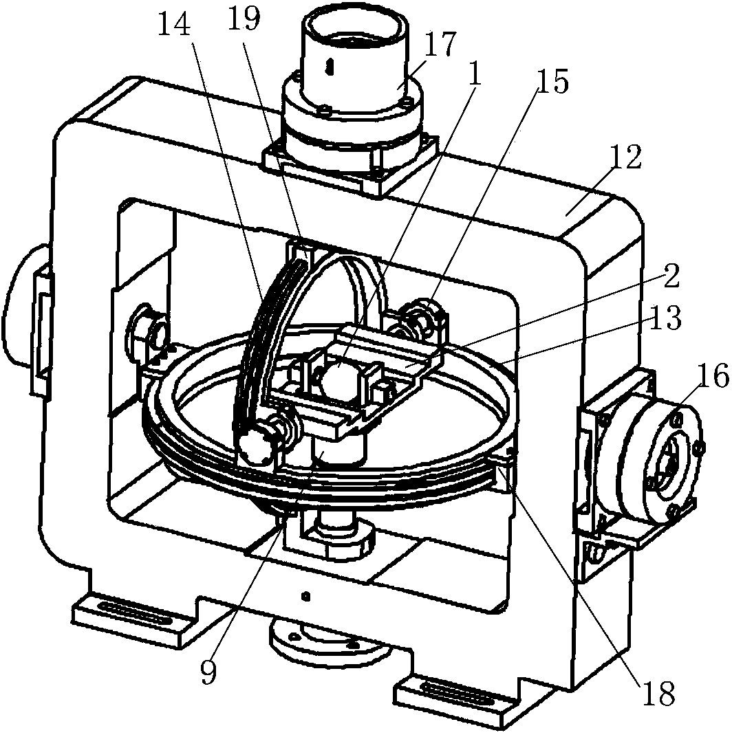
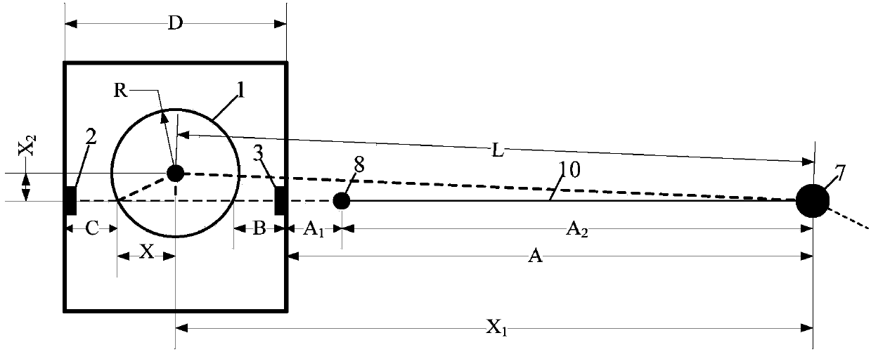
[0033] Such as figure 1 As shown, the present invention provides a series laser tracking measurement system with spherical gyration runout error compensation function, comprising: a horizontal turntable 4 placed on the desktop, a support 9 is installed on the horizontal turntable 4, and a spherical gyration is installed on the support 9 mechanism, the spherical gyration mechanism includes a standard ball 1, a support plate 11 with a central opening, a first displacement sensor 2, a second sensor 3, and a laser head 6, wherein the standard ball 1 is arranged at the center of the support 9, and the support plate 11 The central opening of the standard ball 1 is installed on the bracket 9 after passing through the standard ball 1, and the first displacement sensor 2, the second sensor 3, and the laser head 6 are installed on the support plate 11, wherein the first displa...


PUM


Abstract

The invention discloses a laser tracking measurement system having the spherical revolution bounce error compensation function and a compensation method thereof. The laser tracking measurement system comprises a horizontal rotary table; a support is installed on the horizontal rotary table; and a spherical revolution mechanism is installed at the support. The spherical revolution mechanism includes a standard ball, a support plate with an opening at the center, a first displacement sensor, a second displacement sensor, and a laser head; the standard ball is arranged at the center of the support; the central opening of the support plate passes through the standard ball and then is installed at the support; the first displacement sensor and the second displacement sensor are arranged at a reversed extension line of a laser beam emitted by the laser head and are respectively arranged at the two sides of the standard ball. The standard ball is not contacted with the support plate because of the location at the center of the spherical revolution mechanism and the distance between the sphere center and the target point is obtained precisely based on the measurement value and the calibration value, so that the spherical revolution bounce error of the spherical laser tracking mechanism is compensated and thus the good measurement precision can be realized under the circumstances that the revolution bounce of the laser tracking mechanism is high.

Description

technical field [0001] The invention relates to the field of laser tracking measurement, in particular to a laser tracking measurement system with the function of compensating spherical gyration runout errors. Background technique [0002] In the manufacturing process of large-scale equipment such as aircraft, water turbines, wind turbines, and solar panels, it is necessary to accurately measure the size of the parts in production and the pose during assembly. [0003] Among the currently used large-scale measuring equipment, laser tracking measurement equipment has been widely used in industrial production due to its high precision and wide measurement range. Laser tracking measurement mainly includes spherical coordinate measurement method and multilateral distance method. In the coordinate measurement method, the angle error in the measurement process will be enlarged proportionally with the increase of the measurement distance; in the multilateral distance measurement me...

Claims


Application Information

Patent Timeline
Patent Type & Authority Applications(China)
IPC IPC(8): G01B11/00G01C21/00G01C25/00
Inventor 刘志刚张雄飞周扬理李逸群龚海吕涛
Owner XI AN JIAOTONG UNIV
Learn More