Modular radiation heat exchange terminal and waste heat recovery radiation pipe network heat pump system

A waste heat recovery system and radiation heat exchange technology, applied in heating systems, hot water central heating systems, air conditioning systems, etc., can solve the problems of industrial waste heat not being used, polluting the environment, etc., to improve energy utilization, reduce comprehensive The effect of coal consumption and reduction of upper tower flow

Inactive Publication Date: 2017-03-29
HENAN AIMOKA ENERGY SAVING TECH
View PDF5 Cites 0 Cited by
  • Summary
  • Abstract
  • Description
  • Claims
  • Application Information

AI Technical Summary

Problems solved by technology

[0003] Aiming at the current problem that a large amount of industrial waste heat cannot be used and pollutes the environment, the present invention provides a waste heat recovery radiation pipe network heat pump system, which utilizes industrial waste heat recovery from power plants and ground source water for heating and cooling, saves energy and reduces consumption, and is an energy-saving, environmentally friendly , comfortable air conditioning system

Method used


Image

  • Modular radiation heat exchange terminal and waste heat recovery radiation pipe network heat pump system
  • Modular radiation heat exchange terminal and waste heat recovery radiation pipe network heat pump system
  • Modular radiation heat exchange terminal and waste heat recovery radiation pipe network heat pump system

Examples


Embodiment Construction

[0018] Below in conjunction with accompanying drawing, the present invention will be further described.

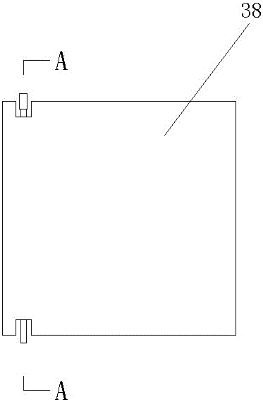
[0019] Such as figure 2 , image 3 , Figure 4 As shown, a modular radiation heat exchange terminal 14 is composed of a plurality of radiation heat exchange modules 38, and each heat exchange module 38 is composed of several three-type copolymer polypropylene dry pipes 39 arranged horizontally and several branch pipes 40 arranged vertically. and a gypsum protective layer 41 between the main pipe and branch pipes; wherein, the distance between adjacent main pipes 39 is 150--170mm, and the distance between adjacent branch pipes is 35-45mm.

[0020] Preferably, the distance between adjacent main pipes 39 is 165 mm, and the diameter of a single main pipe is Φ15 mm; the distance between adjacent branch pipes is 40 mm, and the diameter of a single branch pipe is Φ4 mm.

[0021] Such as Figure 1-Figure 4 As shown, a waste heat recovery radiant pipe network heat pump system ...


PUM


Abstract

A waste heat recovery radiation pipe network heat pump system using a modularized radiation heat exchange terminal comprises a waste heat recovery system, wherein the waste heat recovery system is used for recovering energy from waste heat of circulating cooling water of a power plant, heating water at the temperature from 29 DEG C to 34 DEG C is obtained and conveyed into a radiation heat exchange pipe network water distributor which is connected with the modularized radiation heat exchange terminal, and the heating water flowing out of the modularized radiation heat exchange terminal passes through a water collector I and then enters a self-drooping radiation heat exchange humidity-adjusting cabinet water distributor; an outlet of the self-drooping radiation heat exchange humidity-adjusting cabinet water distributor is connected with an inlet of a self-drooping radiation heat exchange humidity-adjusting cabinet, an outlet of the self-drooping radiation heat exchange humidity-adjusting cabinet is connected with an inlet of a water collector II, and finally the water collector II is used for conveying the heating water into the waste heat recovery system again. The waste heat recovery radiation pipe network heat pump system is environmentally friendly, saves energy, lowers water loss of a cooling tower, reduces the flow of the circulating cooling water getting in the tower, reduces power consumption of the circulating cooling water, recovers the exhausted waste heat of the circulating cooling water, increases the energy utilization rate of the power plant, reduces comprehensive coal consumption, makes use of waste heat recovery, saves 40% of energy compared with a traditional air-conditioner heat pump system, and is significant in energy-saving effect.

Description

technical field [0001] The invention relates to the field of waste heat utilization heat pump technology and air conditioning, in particular to a waste heat recovery radiation pipe network heat pump system. Background technique [0002] With the continuous improvement of human living standards, the requirements for living, travel and living environment are getting higher and higher, and the demand for energy is also increasing. The energy crisis has become a major problem facing human beings. To achieve a comfortable living environment The improvement of energy consumption while reducing the demand for energy has become a new requirement for the development and application of energy-saving and environmental protection technologies. At present, a large amount of industrial waste heat is discharged into the air, which not only pollutes the environment, but also wastes a lot of energy. Contents of the invention [0003] Aiming at the current problem that a large amount of in...

Claims


Application Information

Patent Timeline
Patent Type & Authority Patents(China)
IPC IPC(8): F25B29/00F24F5/00F24D3/18F24F13/00
CPCY02P80/15
Inventor 张辉李华伟高春来高丽
Owner HENAN AIMOKA ENERGY SAVING TECH
Why Eureka
Try Eureka