Device and method for joint treatment between vertical structure and horizontal structure

A joint treatment and vertical structure technology, which is applied in the processing of building materials, building construction, construction, etc., can solve the problems that affect the quality of the project and the joints are difficult to deal with, and achieve construction quality assurance, repair cracks, and easy operation Effect

Active Publication Date: 2014-04-23
NO 2 CONSTR GRP CO LTD OF SHANGHAI CONSTR GRP
View PDF6 Cites 4 Cited by
  • Summary
  • Abstract
  • Description
  • Claims
  • Application Information

AI Technical Summary

Problems solved by technology

[0007] Aiming at the existing reverse method of pouring columns in stages, the joints at the joint surface between beams, slabs and columns are difficult to deal with, which affects the quality of the project

Method used


Image

  • Device and method for joint treatment between vertical structure and horizontal structure
  • Device and method for joint treatment between vertical structure and horizontal structure

Examples


Embodiment Construction

[0026] A joint treatment device and method between a vertical structure and a horizontal structure proposed by the present invention will be further described in detail below in conjunction with the accompanying drawings and specific embodiments. Advantages and features of the present invention will be apparent from the following description and claims. It should be noted that all the drawings are in a very simplified form and use imprecise scales, and are only used to facilitate and clearly assist the purpose of illustrating the embodiments of the present invention.

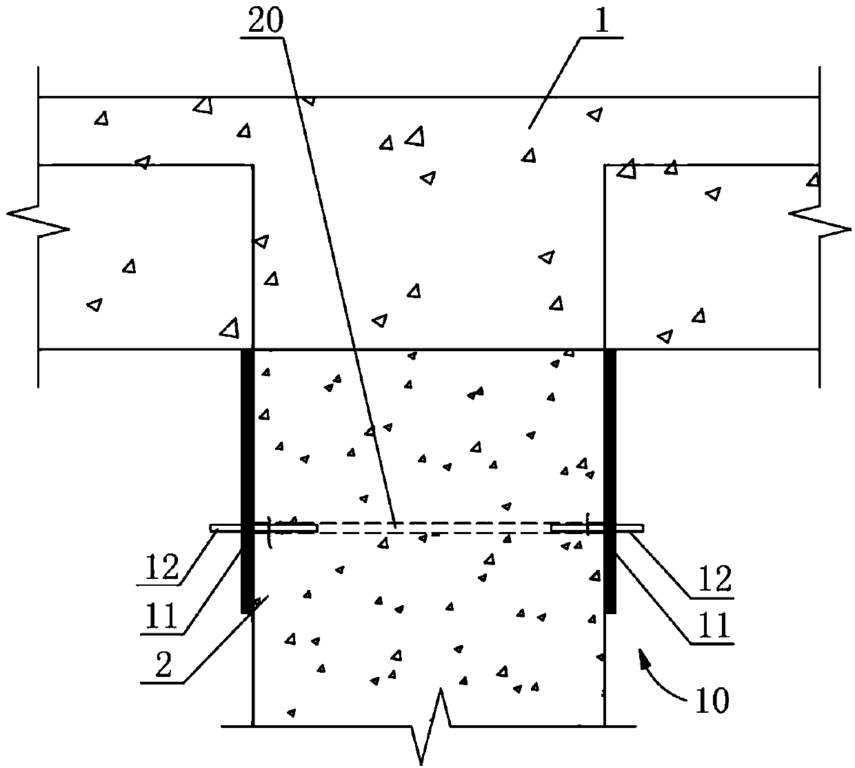
[0027] to combine figure 1 and figure 2 Describe the joint treatment equipment between the vertical structure and the horizontal structure of the present invention. This embodiment takes the treatment process of the joint between the beam plate 1 and the column 2 in the reverse method as an example. The joint treatment equipment 10 of this embodiment It includes an annular formwork assembly 11 capable of cove...


PUM


Abstract

The invention provides a device and method for joint treatment between a vertical structure and a horizontal structure and relates to the technical field of site preparation of building materials or building components. The problem that in existing reverse construction method gradation pouring cylinder construction, a joint at the position of a junction surface between a beam plate and a cylinder is difficult to process, and engineering quality is influenced is solved. The joint treatment device comprises an annular formwork module capable of densely covering the outer side of the joint, at least one grouting pipe and a slurry outlet pipe, wherein the at least one grouting pipe and the slurry outlet pipe are respectively arranged on the annular formwork module. The grouting pipes and the slurry outlet pipe penetrate through and are fixedly connected to a side wall of the annular formwork module. The joint treatment method comprises a first step of providing the joint treatment device; a second step of clearing the outer surface of the vertical structure and blocking the edge of the joint; a third step of mounting the joint treatment device, assembling the annular formwork module to enable annular formwork module to tightly wrap the joint, and enabling one end of the grouting pipe and one end of the slurry outlet pipe which penetrate through the annular formwork module to be towards a cavity where the joint is located; and a fourth step of injecting concrete through the grouting pipe to block the joint.

Description

technical field [0001] The invention relates to the technical field of on-site preparation of building materials or building components, in particular to a joint processing device and method between a vertical structure and a horizontal structure. Background technique [0002] In construction engineering, the quality of finished products of columns is the key to the quality of vertical structural engineering. Since the reverse method is characterized by pouring concrete in stages, there will be a certain gap between the beam-slab and the column, and the gap is generally located 500mm below the beam. The reasons are as follows: [0003] 1. All pumped concrete is used on the construction site, and the concrete slump is large (high fluidity) and other reasons cause the concrete to shrink greatly after construction; [0004] 2. Due to the shortcomings of the concrete material itself, the bleeding and exothermic properties of the hydration reaction take away a certain amount of ...

Claims


Application Information

Patent Timeline
IPC IPC(8): E04G21/02E04B1/682
Inventor 谢德强潘磊
Owner NO 2 CONSTR GRP CO LTD OF SHANGHAI CONSTR GRP
Why Eureka
Try Eureka