
Self-traveling type intelligent continuous dynamic compactor

A dynamic tamping machine and self-propelled technology, which is applied in the field of foundation soil survey, soil protection, construction, etc., can solve the problems of large influence on the surrounding structure, poor off-road performance and stability of the loader, and time-consuming problems, and achieve the tamping depth It has the effect of large impact depth, good off-road performance and stability, and easy operation

Active Publication Date: 2014-04-23
西安长大公路养护技术有限公司
View PDF5 Cites 4 Cited by
  • Summary
  • Abstract
  • Description
  • Claims
  • Application Information

AI Technical Summary

Problems solved by technology

Ordinary road rollers have the advantages of good compaction continuity and high surface flatness. At the same time, if it is a vibratory road roller, it can also increase the effective depth of compaction and improve compaction efficiency. At present, Germany has developed BTM compaction monitoring equipment, which can real-time Self-inspection and control of compaction, but the equipment price is high, and the compaction work of ordinary road rollers is low, and it needs to be compacted back and forth to achieve the compaction effect. The effective depth of compaction is also limited, generally 1m ~ 2m
[0004] The dynamic tamping machine in the prior art has a large impact depth of tamping, which can reach 5m to 10m, and a single point compaction degree is high. Generally, it only needs to be tamped 1 to 3 times to achieve the required compaction degree, but in the prior art The dynamic compaction machine requires large-scale mechanical operations such as cranes or gantry frames. At the same time, it is generally compacted at a single point, resulting in low compaction efficiency. At the same time, it is troublesome to detect the degree of compaction and has high requirements for the site. Personnel are highly dangerous and have a great impact on surrounding buildings
The impact rollers in the prior art have large compaction thickness and compaction impact depth, and good continuity, but require large-scale mechanical traction, and at the same time have a large impact on the surrounding structure, and have insufficient compaction detection efficiency.
However, other small compactors in the prior art are only suitable for local reinforcement and repair of road surface potholes. The application range is small and the compaction effect is poor. It is time-consuming and cannot meet the needs of actual use.
[0005] In order to solve the above problems, the Chinese patent application No. 201210234020.6 discloses an intelligent continuous dynamic compaction machine. The dynamic compaction machine can intelligently and continuously compact, and at the same time, the compaction work is relatively large, and the compaction thickness and compaction influence depth are large. However, in During use, it was found that the dynamic compaction machine still has the following defects and deficiencies: (1) The dynamic compaction machine uses a loader as the traction device. Due to the poor off-road performance and stability of the loader, the climbing force is small, and it is difficult to turn The radius is large, and after stopping at one position, the tamping mechanism cannot rotate 360° on it, the flexibility is poor, and it cannot walk by itself according to the predetermined walking distance and walking speed, and the conversion of the tamping point is inconvenient , thus limiting the popularization and use of the dynamic compaction machine; (2) One end of the soft connector connected to the tamper in the dynamic compaction machine is fixedly connected to the frame. During the compaction process, the traction force of the tamper to the frame is large. , it is easy to cause the deformation of the frame, and finally the falling position of the rammer will be different from the expected position, which will affect the compaction accuracy

Method used


Image

  • Self-traveling type intelligent continuous dynamic compactor
  • Self-traveling type intelligent continuous dynamic compactor
  • Self-traveling type intelligent continuous dynamic compactor

Examples


Embodiment Construction

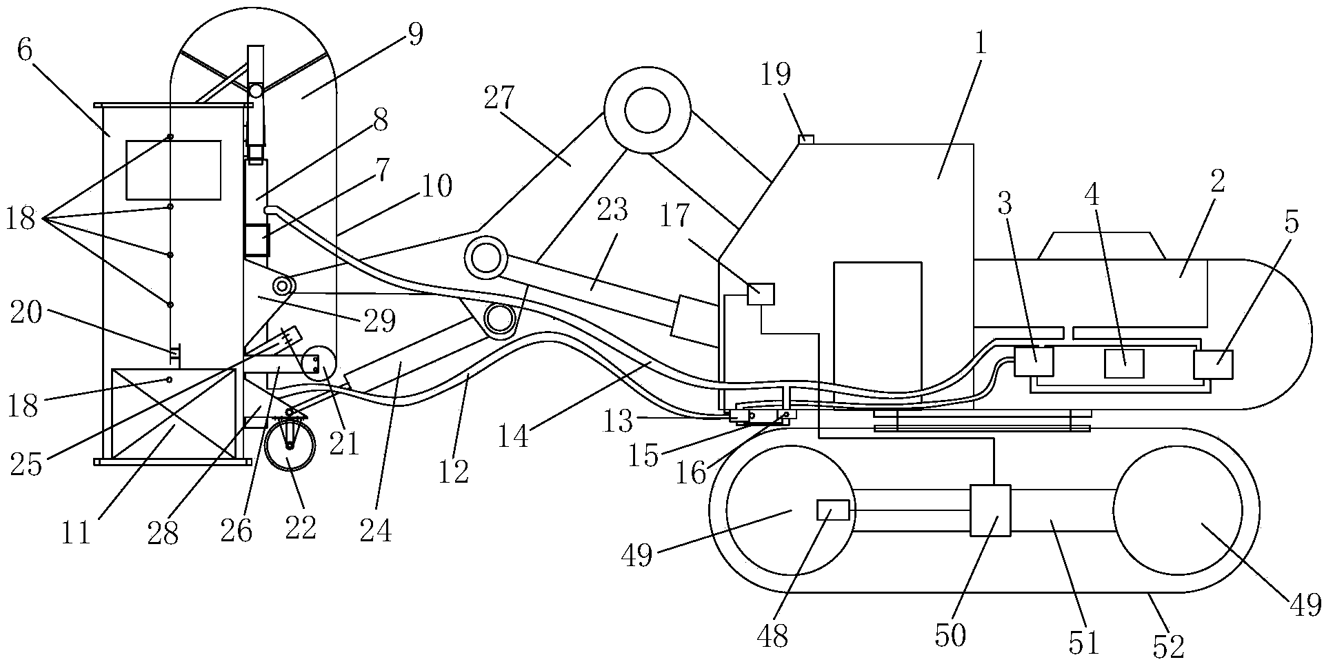
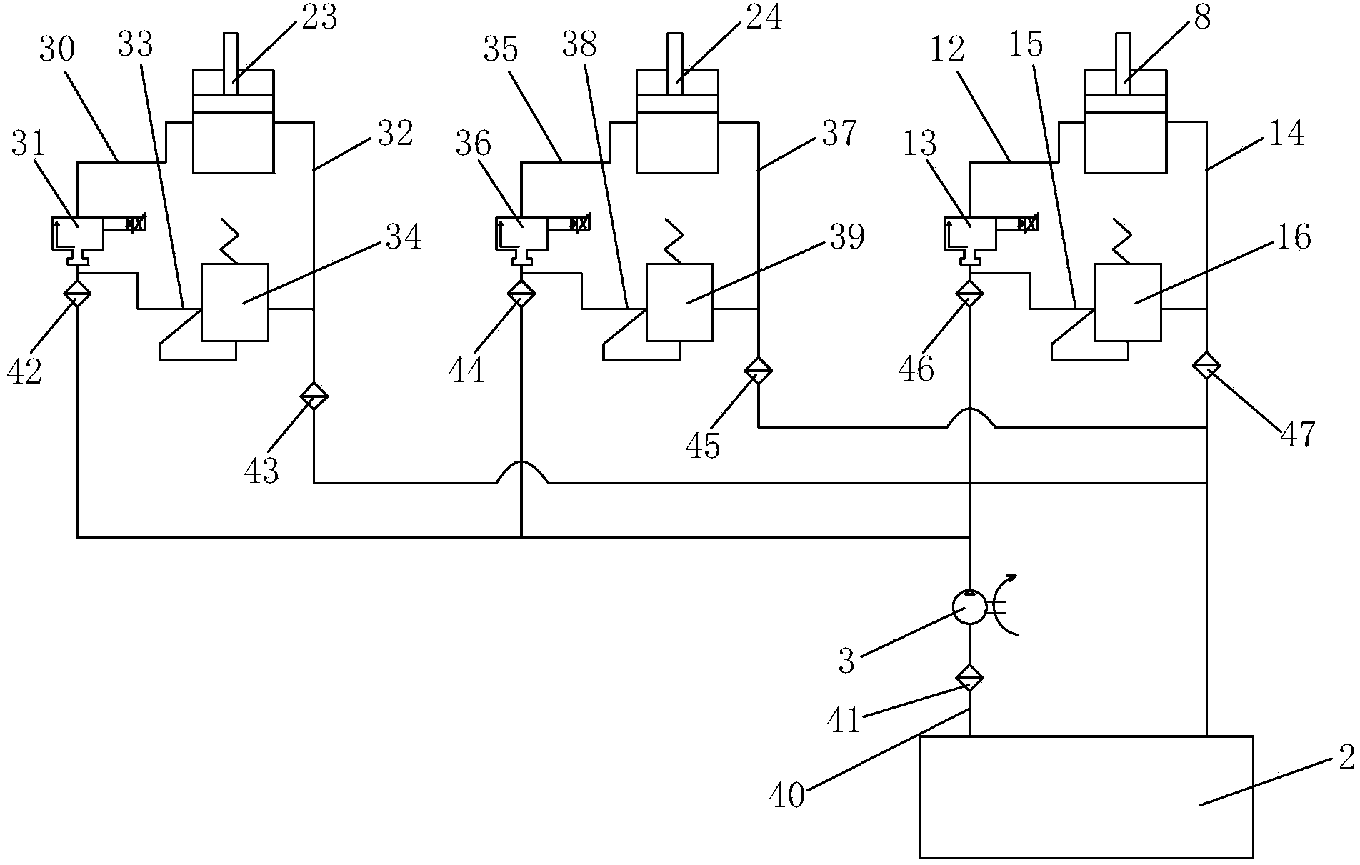
[0062] like figure 1 As shown, the present invention includes a crawler excavator 1, a crawler excavator power system and a crawler excavator self-propelled mechanism, and is connected to the crawler excavator 1 through a connecting arm 27, a first oil cylinder 23 and a second oil cylinder 24 The tamping mechanism of the crawler excavator; the crawler excavator power system includes a fuel tank 2, an oil pump 3 and a radiator 4 connected to the fuel tank 2, and an engine 5 connected to the oil pump 3; the crawler excavator self-propelled mechanism includes a walking frame 51 , the walking wheel 49 that is connected on the walking frame 51 and the walking track 52 that is connected on the walking wheel 49, and the self-propelled control system that is used to control the self-propelling of the walking wheel 49 and the walking track 52; the compacting mechanism includes Frame 6, the oil cylinder fixing flange 7 that is connected on the frame 6 and the 3rd oil cylinder 8 that is ...


PUM


Abstract

The invention discloses a self-traveling type intelligent continuous dynamic compactor which comprises a crawler excavator, a crawler excavator power system, a crawler excavator self-traveling mechanism and a compaction mechanism, wherein the crawler excavator power system comprises an oil tank, an oil pump, a heat dissipater and an engine; the crawler excavator self-traveling mechanism comprises a traveling frame, traveling wheels, a traveling crawler and a self-traveling control system; the compaction mechanism comprises a stander, a third oil cylinder, a movable pulley, a soft connection body, a fixed pulley and a rammer; a stander is connected with a supporting wheel and is provided with a compaction density detection system; a hydraulic system and an intelligent control system are arranged on the crawler excavator; a third connection plate is connected to the stander; one end of a connection arm is connected with the crawler excavator, and the other end of the connection arm is connected with the third connection plate. The self-traveling type intelligent continuous dynamic compactor is easy to use and operate, has a self-traveling function and can intelligently realize continuous compaction; furthermore, the compaction power is higher, and the compaction thickness and the compaction influence depth are large; the self-traveling type intelligent continuous dynamic compactor can accurately detect the compaction density and work stably and reliably.

Description

technical field [0001] The invention belongs to the technical field of engineering machinery, in particular to a self-propelled intelligent continuous dynamic compaction machine. Background technique [0002] The compaction quality of highway subgrade filling will directly affect the settlement deformation and stability of subgrade, so the compaction degree of subgrade filling must be strictly controlled during construction. [0003] At present, the relevant equipment for roadbed compaction in my country is mainly ordinary road rollers (including single-wheel, double-wheel, rubber wheels), dynamic compactors, impact rollers, and other small machinery. Ordinary road rollers have the advantages of good compaction continuity and high surface flatness. At the same time, if it is a vibratory road roller, it can also increase the effective depth of compaction and improve compaction efficiency. At present, Germany has developed BTM compaction monitoring equipment, which can real-ti...

Claims


Application Information

Patent Timeline
Patent Type & Authority Applications(China)
IPC IPC(8): E02D3/046E02D1/00
Inventor 吴超凡李鹏辉袁锦浪余宏波王志刚杨明艳王水赵耀辉
Owner 西安长大公路养护技术有限公司
Learn More