Dynamical system structure suitable for vertical take-off and landing aircraft and control method thereof

A power system, vertical take-off and landing technology, applied in the direction of vertical take-off and landing aircraft, aircraft, motor vehicles, etc., can solve problems such as difficult to guarantee stability and reliability, affect the flight quality of level flight, and cannot improve flight efficiency, etc., to achieve control The method is mature and reliable, the effect of good hovering performance in the air and good vertical take-off and landing performance

Inactive Publication Date: 2014-04-23
XI AN JIAOTONG UNIV
View PDF6 Cites 24 Cited by
  • Summary
  • Abstract
  • Description
  • Claims
  • Application Information

AI Technical Summary

Problems solved by technology

[0004] Most of the existing vertical take-off and landing aircraft adopt single-axis, double-axis, or three-axis vertical take-off and landing structural layout forms with high control difficulty, not only the stability and reliability are difficult to guarantee in the vertical take-off and landing mode, but also The method will cause the structure of the aircraft to be different from ordinary fixed-wing aircraft, which is too complicated, which will seriously affect the aerodynamic layout in the fixed-wing mode, thereby seriously affecting the flight quality in level flight
On the other hand, most of the existing vertical take-off and landing aircraft are limited by their structural design, so there is no way to use a large wingspan, so that the effective wing area cannot be increased, so that its flight efficiency cannot be improved. There is a big difference compared to the plane

Method used


Image

  • Dynamical system structure suitable for vertical take-off and landing aircraft and control method thereof
  • Dynamical system structure suitable for vertical take-off and landing aircraft and control method thereof
  • Dynamical system structure suitable for vertical take-off and landing aircraft and control method thereof

Examples


Embodiment

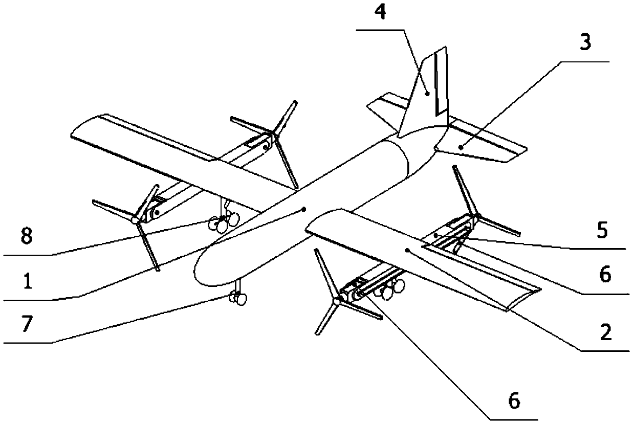
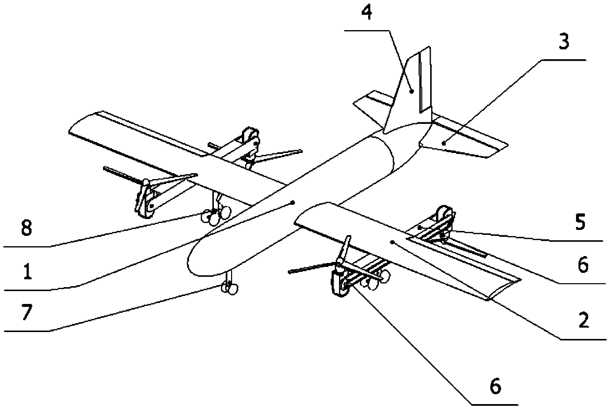
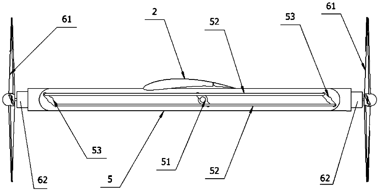
[0026] The present invention provides a power system structure suitable for a vertical take-off and landing aircraft, including propellers 61 for providing power. The straight state is tilted upwards to a horizontal state, and the propeller 61 positioned at the rear side of the main wing 2 can be tilted downwards from a vertical state to a horizontal state; The propeller 61 on the rear side of the wing adopts anti-installation to provide thrust and lift for the aircraft; the respective tilting of the propeller 61 on the front and rear sides of the main wing is carried out synchronously; the propeller 61 on the front and rear sides of the main wing is driven by one engine or two The engines are driven separately. The following is a detailed introduction according to the accompanying drawings.

[0027] according to figure 1 , figure 2 As shown, the vertical take-off and landing vehicle of the present invention adopts conventional aerodynamic layout: comprising fuselage 1, ma...


PUM


Abstract

The invention provides a dynamical system structure suitable for a vertical take-off and landing aircraft and a control method thereof. The dynamical system structure suitable for the vertical take-off and landing aircraft comprises propellers for providing power, wherein the propellers are configured at the front side and rear side of a main aerofoil at two sides of an aircraft; the propeller positioned at the front side of the main aerofoil can be oblique upward from the vertical state to the horizontal state; the propeller positioned at the rear side of the main aerofoil can be oblique downward from the vertical state to the horizontal state. According to the invention, by the design, the layout and the control mode which are similar to the existing most mature and stable X-type four-shaft aircraft under the vertical take-off and landing mode are realized, but also the layout type, the effective aerofoil area and the integral structure of the traditional and reliable fixed aerofoil aircraft are retained maximally under the level flight, therefore, compared with other vertical take-off and landing aircrafts, the dynamical system structure suitable for the vertical take-off and landing aircraft has the advantages of reasonable layout type, simple structure, mature and reliable control mode, more stable flight, remote voyage, great load and the like.

Description

technical field [0001] The invention belongs to the field of aircraft design, and in particular relates to a power system structure suitable for vertical take-off and landing aircraft and a control method thereof. Background technique [0002] The birth of vertical take-off and landing technology is mainly due to the lack of aircraft taxiing and take-off methods, especially the performance in previous wars, so that the vertical take-off and landing of aircraft has come into people's sight. Direct attacks on enemy airfields in wars such as World War II and the Middle East War made people feel the inadequacy of taxiing aircraft requiring runways, while the Cold War was the catalyst for VTOL technology. In the 1950s and 1960s after World War II, under the shadow of a nuclear war that was likely to break out, people worried that a nuclear war would cause damage to the airport and conventional aircraft could not be dispatched, so the vertical take-off and landing technology of fi...

Claims


Application Information

Patent Timeline
IPC IPC(8): B64C27/22B64C29/00B64D27/02
Inventor 张旭超于德弘秦科科汪翔宇杨壮滔任超
Owner XI AN JIAOTONG UNIV
Why Eureka
Try Eureka