
Multifunctional guidewire assemblies and system for analyzing anatomical and functional parameters

A technology of guidewires and components, applied in the field of multifunctional guidewire assemblies and systems for analyzing anatomical and functional parameters, capable of solving problems such as stenosis, increased CFR, etc.

Inactive Publication Date: 2014-04-16
ANGIOMETRIX CORP
View PDF18 Cites 21 Cited by
  • Summary
  • Abstract
  • Description
  • Claims
  • Application Information

AI Technical Summary

Problems solved by technology

In other words, only those stenosis that resulted in the most significant increase in CFR after treatment with the combination

Method used


Image

  • Multifunctional guidewire assemblies and system for analyzing anatomical and functional parameters
  • Multifunctional guidewire assemblies and system for analyzing anatomical and functional parameters
  • Multifunctional guidewire assemblies and system for analyzing anatomical and functional parameters

Examples


Embodiment 1

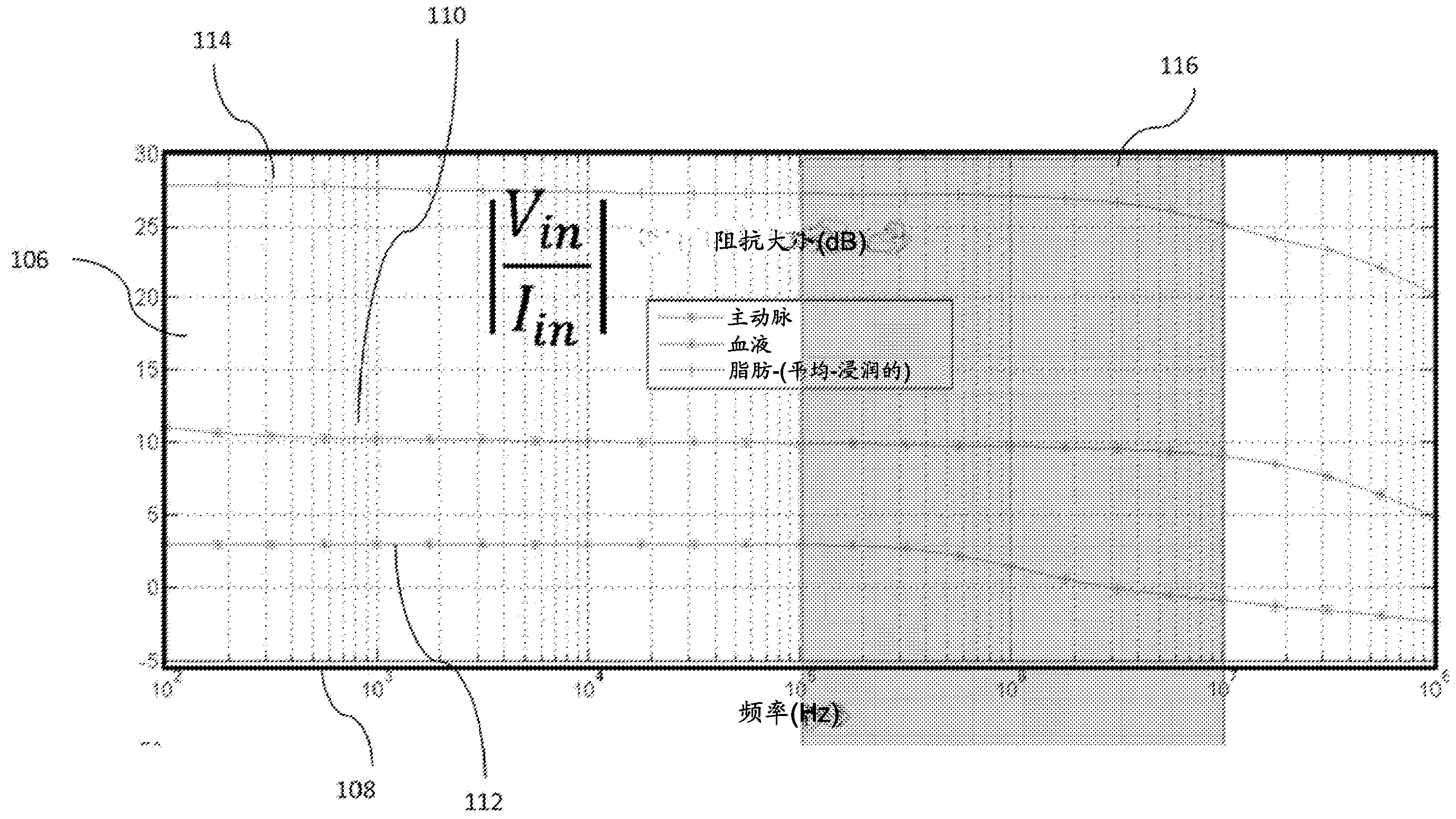
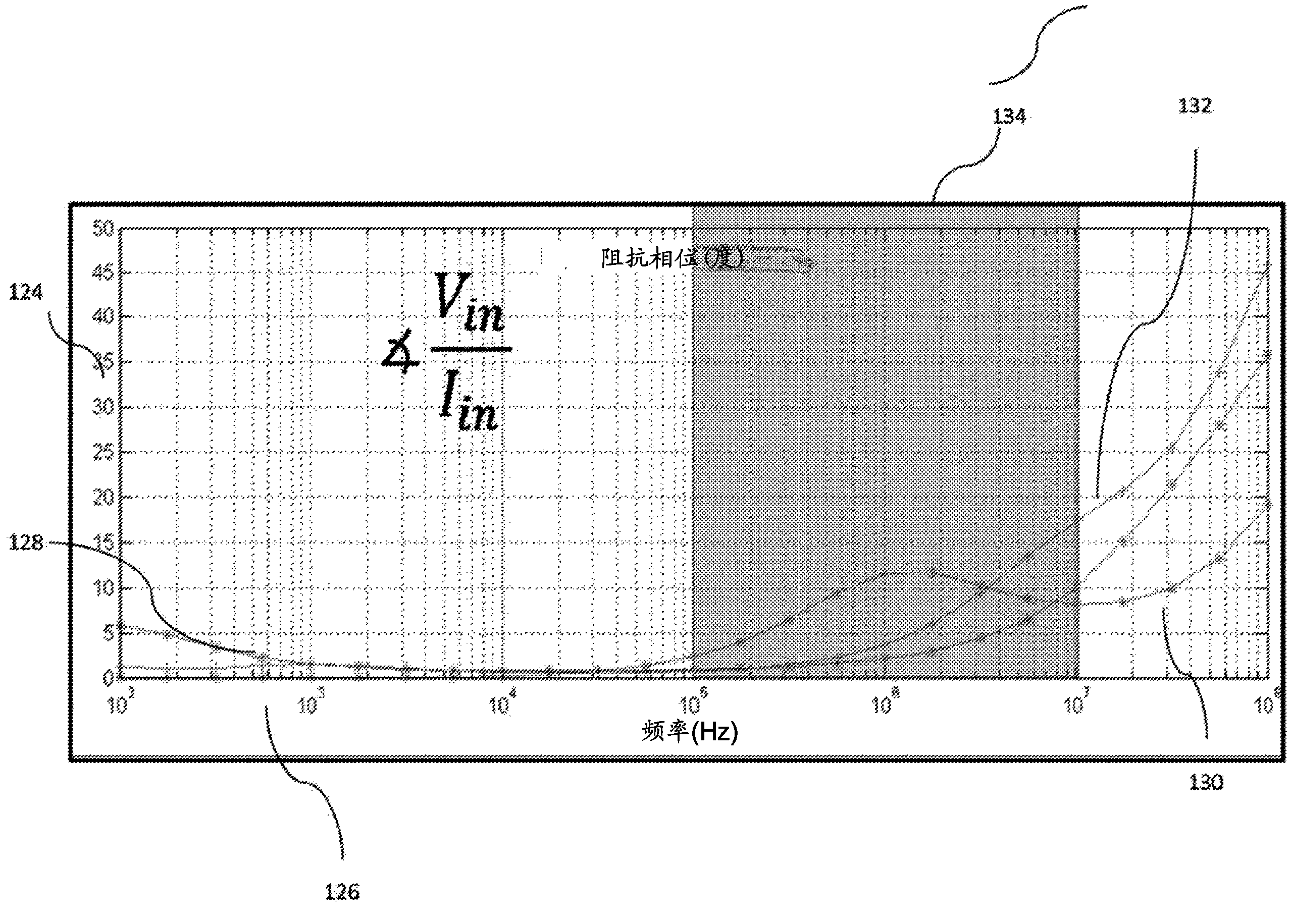
[0266] In an exemplary implementation, the excitation frequency band is selected between 40KHZ (FL) and 10MHZ (FH) based on the electrical characteristics of blood, tissue, and fat. The 16-bit D / A converter is selected to work at FS (=20MHZ) sampling rate. The selected D / A converter accepts an offset binary sequence (0X0000 for the lowest value and 0XFFFF for the highest value). According to the one-bit pseudo-random mode, the most significant byte of the converter is triggered, and the next bit is permanently kept at logic 1. All other bits are kept at logic 0. Therefore, depending on the 0 or 1 from the pseudo-random generator, the D / A input switches between 0X4000 and 0XC000. The pseudo-random generator is located on the back-end entity and consists of a series of 9 D flip-flops called FLOPs to represent the 9-tap pseudo-random sequence. The resulting sequence is a maximum length pseudo-random sequence with a length of L=511 (29-1). The generator polynomial used to gener...

Embodiment 2

[0275] In another implementation, such as Figure 15 As shown in, NFREQ (=256) discrete tones of equal amplitude are used to construct an OFDM sequence and each tone is in a random phase. Adjust the phase angle with respect to each tone to obtain a PAR lower than 1.4. The construction of an OFDM sequence can be done simply by adding all discrete tones together or by performing IFFT (Inverse Fast Fourier Transform) on a 2Nfreq (=512) complex symmetric sequence, where the first 256 complex numbers are related to the amplitude and phase of a single tone , And the next group of 256 complex numbers is simply the conjugate complex number of the first 256 complex numbers arranged in reverse order ( Figure 15 ). Figure 16 Shows the time-domain signal sampled at FS (=20MHZ) twice the maximum frequency of interest (FH). The lowest frequency in this sequence is FL (=FS / 2NFREQ=39.0625KHZ). Time-domain OFDM sequences can also be generated at a higher sampling rate using an appropriate si...


PUM


Abstract

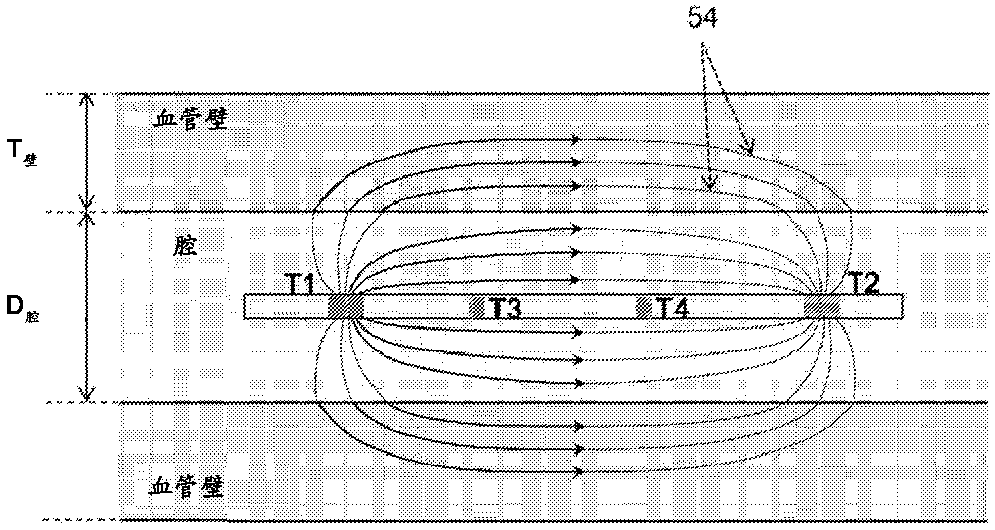
Multifunctional guidewire assemblies and system for analyzing anatomical and functional parameters are described. Using a single guidewire, functional and anatomical measurements and identification of lesions may be made. Functional measurements such as pressure may be obtained with a pressure sensor on while anatomical measurements such as luminal dimensions may be obtained by utilizing an electrode. The vascular network and stenosed lesions may be modeled into an equivalent electrical network and solved based on the measured parameters. Treatment plan options may be constructed where each plan may correspond to the treatment of a subset of particular lesions. The anatomical outcome for each treatment plans may be estimated and the equivalent modified electrical parameters may be determined. Then, each of the electrical networks for each plan may be solved to determine the functional outcome for each treatment plan and the outcomes for all treatment plans may be presented to a physician.

Description

[0001] Cross references to related applications [0002] This application is a partial continuation application of US patent application 13 / 305,630 filed on November 28, 2011. This partial continuation application itself is a partial continuation application of US patent application 13 / 159,298 filed on June 13, 2011. The latter requires U.S. Provisional Patent Application 61 / 383,744 filed on September 17, 2010 has the right of priority and also claims the right of foreign priority for Indian Provisional Patent Application 1636 / CHE / 2010 filed on June 13, 2010. These applications Each of is incorporated into this article by reference. [0003] Incorporated by reference [0004] All publications and patent applications mentioned in this specification are incorporated herein by reference to the same extent as the following: each individual publication or patent application is specifically and individually indicated as being incorporated by reference. [0005] Technical field of invention ...

Claims


Application Information

Patent Timeline
IPC IPC(8): A61B5/00A61B5/296
CPCA61B5/1076A61B5/068A61B5/0538A61M25/1018A61B5/6852A61B5/02007A61M25/10188
Inventor 尼廷·帕蒂尔拉加万·苏帕拉马尼亚恩高塔姆·杜塔
Owner ANGIOMETRIX CORP
Learn More