A visual measurement method for rocket engine nozzle movement and a high-brightness infrared light-emitting device used in the method
A rocket engine and infrared light-emitting technology, which is applied in the directions of measuring devices, photogrammetry/video metrology, surveying and navigation, etc., can solve the problem that the camera image plane cannot correctly identify cooperation targets, etc., and achieve simple structure, clear collection, Effects in simple steps
- Summary
- Abstract
- Description
- Claims
- Application Information
AI Technical Summary
Problems solved by technology
Method used
Image
Examples
specific Embodiment approach 1
[0021] The specific embodiment one, a kind of rocket engine nozzle movement visual measurement method described in this specific embodiment, it comprises the following steps:
[0022] Step 1. Arrange multiple infrared light-emitting points on the outer surface of the rocket engine nozzle, and connect the infrared light-emitting points in parallel with multiple channels to form a light-emitting circuit. Each channel is composed of two infrared light-emitting points and an adjustable voltage divider resistor. In a series structure, the number of the channels is 2 or 3, and the infrared light-emitting point is realized by a high-brightness infrared light-emitting device,
[0023] Step 2, setting an infrared filter before the lens of the image acquisition device,
[0024] Step 3, connect the image acquisition signal output end of the image acquisition device with the image acquisition signal input end of the visual measurement system control computer,
[0025] Step 4. Aim the len...
specific Embodiment approach 2
[0029] Specific embodiment two, combine Figure 7 Describe this specific embodiment, the difference between this specific embodiment and the visual measurement method of a rocket engine nozzle movement described in specific embodiment 1 is that the light-emitting circuit described in step 1 also includes a power supply VCC, a switch S1 and a circuit pass. The off indicator LED1, the power supply VCC is used to supply power to the light-emitting circuit, the switch S1 is used to control the on or off of the light-emitting circuit, the circuit on-off indicator LED1 is connected in series with the switch S1, and is used to display the on or off of the light-emitting circuit status.
specific Embodiment approach 3
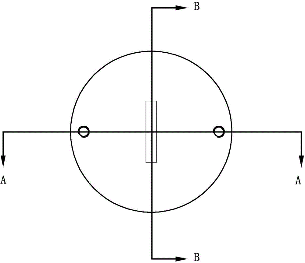
[0030] Specific embodiment three, combine Figure 1 to Figure 6 Illustrate this specific embodiment, the high-brightness infrared light-emitting device used in a kind of rocket engine nozzle motion visual measurement method described in specific embodiment 1 comprises an infrared light-emitting circuit board, an infrared light-emitting diode and a housing, and the infrared light-emitting diode is fixed on On the infrared light-emitting circuit board, the infrared light-emitting diode includes 9 infrared light-emitting cores working in parallel. Both sides of the infrared light-emitting circuit board are processed with symmetrical light holes. The shell includes a shell and a base. The shell is cylindrical structure, the infrared light-emitting circuit board is fixed in the casing, and a through hole is opened in the center of the upper surface of the casing. The positive and negative wires of the infrared light-emitting diode are connected to the external power supply through ...
PUM
 Abstract
Description
Claims
Application Information
 - R&D
- Intellectual Property
- Life Sciences
- Materials
- Tech Scout
- Unparalleled Data Quality
- Higher Quality Content
- 60% Fewer Hallucinations
Browse by: Latest US Patents, China's latest patents, Technical Efficacy Thesaurus, Application Domain, Technology Topic, Popular Technical Reports.
© 2025 PatSnap. All rights reserved.Legal|Privacy policy|Modern Slavery Act Transparency Statement|Sitemap|About US| Contact US: help@patsnap.com


