


Quick Research
Generate reliable direction feasibility study reports for your R&D in just a few steps.

Technical Q&A
Discover and master advanced knowledge NOW. Basics, ideas, possibilities, all at once.

Find Solutions
As an expert in R&D theories, this can generate solutions to your technical problems instantly.

Evaluate Feasibility
Analyze your overall solution with one click, know your potential R&D risks in advance.

Monitor Landscape
Get weekly tech updates, stay abreast of the latest tech innovations and key insights.
Working door and shot peening equipment with same
A technology for working doors and equipment, which is applied in metal processing equipment, special equipment for doors/windows, windows/doors, etc. It can solve the problems of not being able to observe the working conditions of the internal mechanism of the shot blasting equipment, poor sealing of the shot blasting equipment, and real-time monitoring. and other problems to achieve the effect of preventing dust leakage, good sealing effect and ensuring sealing
- Summary
- Abstract
- Description
- Claims
- Application Information
AI Technical Summary
Problems solved by technology
Method used
Image


Examples
Embodiment 1
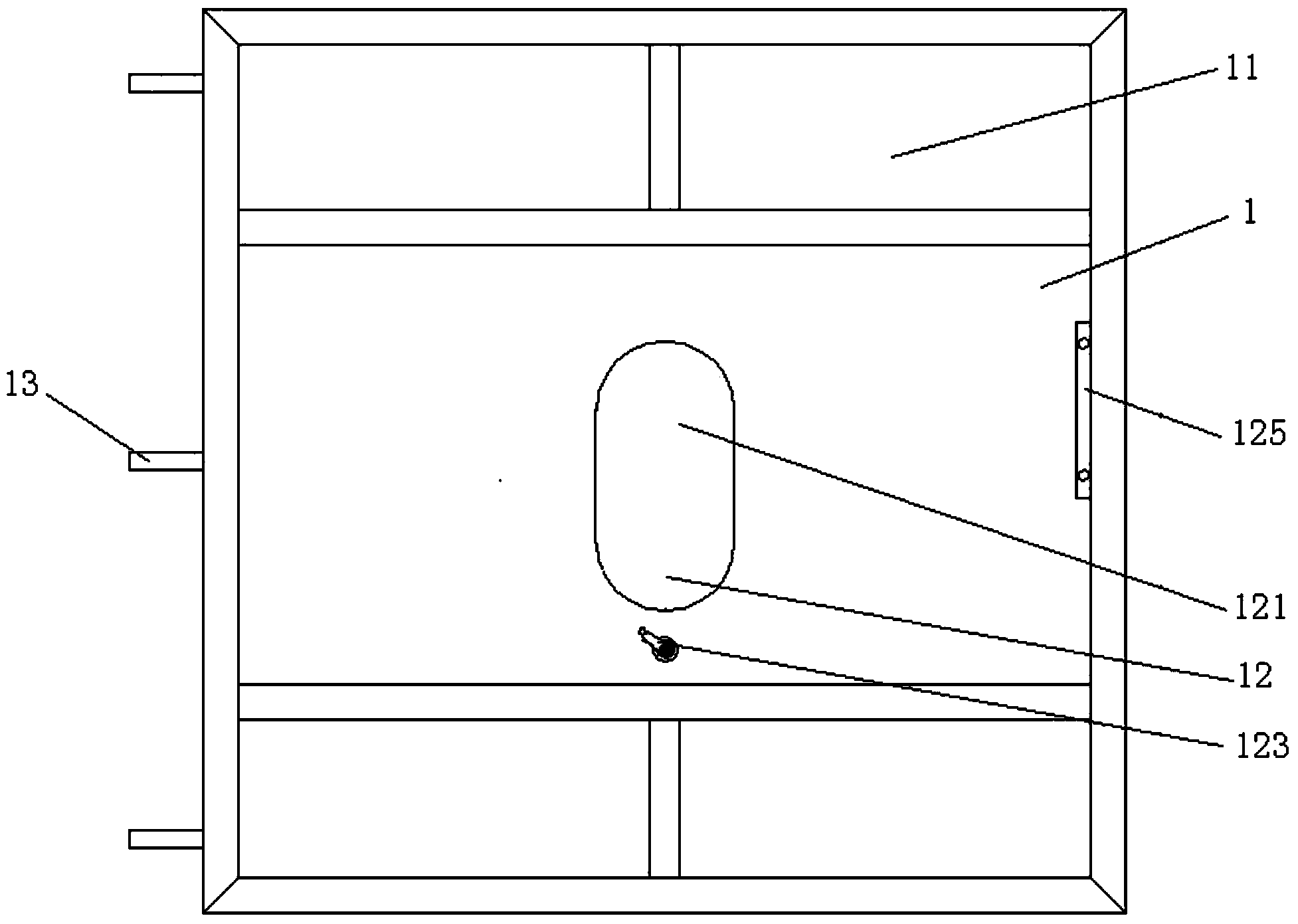
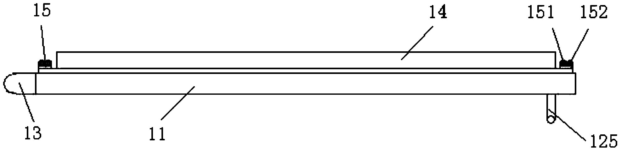
[0032] Figure 1 to Figure 3 It is a structural schematic diagram of the working door of the shot blasting equipment provided in this embodiment. As shown in the figure, the working door 1 of the shot blasting equipment includes a door body 11 on which a hand-operated window assembly 12 is arranged. The manual window assembly 12 includes a glass window 121 installed on the door body 11, a protective plate 122 arranged on the back of the door body 11, a hand crank 123 arranged on the front of the door body 11, and a transmission mechanism 124 connected with the hand crank 123 , the hand crank 123 drives the protective plate 122 to move through the transmission mechanism 124 to block or expose the glass window 121 . The glass window 121 adopts tempered 5mm tempered glass material. A door handle 125 is also provided on the front of the door body 11 .
[0033] The transmission mechanism 124 includes a gear 1241 connected with the hand crank 123 and a rack 1242 fixed on the bott...
Embodiment 2
[0037] Figure 4 and Figure 5 Schematic diagram of the structure of the shot peening equipment provided in this embodiment. As shown in the figure, the shot blasting equipment includes a shot blasting chamber body 2, and the shot blasting equipment working door 1 as described in the first embodiment is arranged on the shot blasting chamber body 2. The shot blasting chamber body 2 is provided with three bearing blocks 3 that match the door lugs 13 of the working door 1. The three door lugs 13 and the three bearing seats 3 are connected in series through the door shaft 4, so that the working door 1 can be wound around the door. The shaft 4 turns over to realize the opening and closing of the working door 1. A bumper mechanism 5 is arranged between the shot blasting chamber body 2 and the working door 1 , and the self-locking and sealing of the working door 1 is realized by the bumper mechanism 5 .
[0038] A travel switch is also arranged between the shot blasting chamber bo...
PUM
 Abstract
Description
Claims
Application Information
 - R&D Engineer
- R&D Manager
- IP Professional
- Industry Leading Data Capabilities
- Powerful AI technology
- Patent DNA Extraction
Browse by: Latest US Patents, China's latest patents, Technical Efficacy Thesaurus, Application Domain, Technology Topic, Popular Technical Reports.
© 2024 PatSnap. All rights reserved.Legal|Privacy policy|Modern Slavery Act Transparency Statement|Sitemap|About US| Contact US: help@patsnap.com