
Radio frequency identification method and system based on wireless communication terminal

A wireless communication terminal and wireless communication technology, applied in the direction of cooperative operation devices, record carriers used by machines, instruments, etc., can solve the problems of short recognition distance, increased production cost, increased label cost, etc., to achieve cost saving and high gain , Increase the effect of recognition distance

Inactive Publication Date: 2014-04-09
范志广
View PDF3 Cites 14 Cited by
  • Summary
  • Abstract
  • Description
  • Claims
  • Application Information

AI Technical Summary

Problems solved by technology

However, the SIM card built-in label method is limited to the size of the SIM card, the recognition distance is short, and a special SIM card needs to be customized, which increases the production cost; the direct attachment of the label method improves the recognition distance and facilitates integrated production, but it also needs to be increased. The cost of the label itself
In addition, in both methods, the mobile phone or SIM card is required to bind the data information of the RFID tag, which limits the flexibility and application range of the radio frequency identification function of the wireless communication terminal.

Method used


Image

  • Radio frequency identification method and system based on wireless communication terminal
  • Radio frequency identification method and system based on wireless communication terminal
  • Radio frequency identification method and system based on wireless communication terminal

Examples


Embodiment Construction

[0022] Referring to the attached schematic diagram and aiming at an example of implementing an RFID radio frequency identification system on a GSM / GPRS wireless communication terminal, the present invention will be further described in detail below.

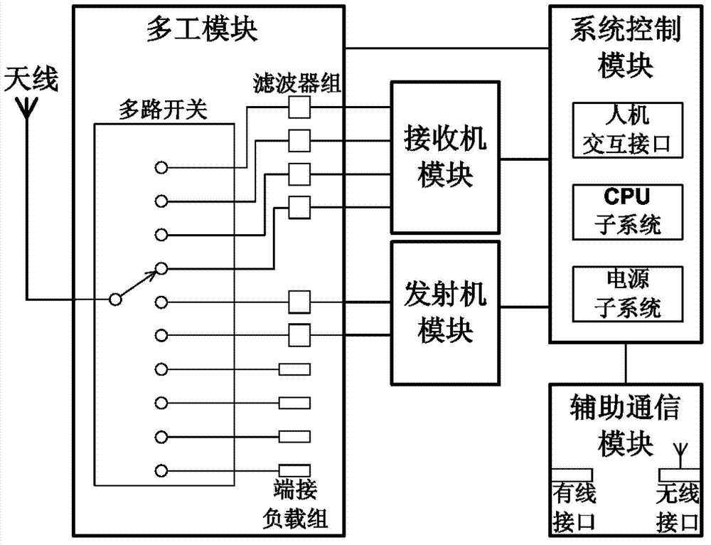
[0023] Such as figure 1 As shown, the wireless communication terminal of the present invention integrates 850MHz, 900MHz, 1800MHz, 1900MHz four-band GSM / GPRS wireless communication functions and 800 / 900MHz frequency band RFID tag functions on the same hardware platform, and cooperates through software design, so that the wireless communication terminal It also has the function of RFID tags. The main components of the wireless communication terminal include: 1. Antenna, which supports GSM / GPRS / RFID wide-band work; 2. Multiplexing module, which is composed of a multi-channel switch, a terminal load group and a filter group. By switching the receiver module, The transmitter module or the connection signal path of the terminal load ...


PUM


Abstract

The invention discloses a radio frequency identification method and system based on a wireless communication terminal. According to solved technical problems, an RFID tag function of the wireless communication terminal is extended; the identification distance of the RFID tag function is increased; and a binding restriction with RFID tag data information is eliminated. According to the method provided by the invention, the wireless communication terminal controls an internal switch of a multi-tasking module to switch a signal path or switch the working state of a receiver and transmitter module; the terminating impedance of an antenna changes corresponding to the RFID data information to carry out reverse scattering communication; and direct extension is carried out to realize the tag function. The antenna of the wireless communication terminal has the advantages of free shape and size design and high gain, thus the identification distance of the RFID tag function is increased. According to the system provided by the invention, the RFID tag data information is updated and generated according to a user need, and is dynamically configured by a networking server. Compared with the prior art, the method and the system, which are provided by the invention, has the advantages that the cost of tag integration is saved; the identification distance is increased; the data information binding restriction is eliminated; and economic, flexible and reliable radio frequency identification is realized.

Description

technical field [0001] The present invention relates to a communication method and system, in particular to a method and system for radio frequency identification and information transmission based on a wireless communication terminal. Background technique [0002] Radio frequency identification (RFID) is a non-contact information identification transmission technology, and its basic system includes two parts: RFID transponder and RFID reader. RFID transponders, also known as RFID tags, store the unique identifier data of attached target objects (such as commodities, goods, certificates, etc.), and can also store specific application data information of target objects, such as commodity names, production dates, Product origin, manufacturer, etc.; RFID readers, also known as RFID readers, communicate with RFID tags in a non-contact manner through electromagnetic waves to read their unique identifiers and application data information. According to the frequency band of electr...

Claims


Application Information

Patent Timeline
Patent Type & Authority Applications(China)
IPC IPC(8): G06K17/00G06K19/07
Inventor 范志广
Owner 范志广
Learn More