Experimental device for simulating bolt-connected disk-and-drum rotor of aero-engine

An aero-engine and experimental device technology, applied in the field of rotor dynamics, can solve the problem of not considering the structural characteristics of the thin-walled cylindrical shell of the drum, the inability to characterize the structural characteristics of the flange-bolt connection, and the inability to truly reflect the dynamic characteristics of the disc-drum rotor and stress distribution characteristics

Active Publication Date: 2014-04-09
TSINGHUA UNIV
View PDF5 Cites 24 Cited by
  • Summary
  • Abstract
  • Description
  • Claims
  • Application Information

AI Technical Summary

Problems solved by technology

The above two literatures focus on the influence of bolt connection on the dynamic characteristics of the rotor, without considering the structural characteristics of the thin-walled cylindrical shell of the drum, and the rotor test benches in the literature are all connected by external flanges, which is different from the actual disc-drum rotor. Inner flange connection
The above-mentioned structura...

Method used


Image

  • Experimental device for simulating bolt-connected disk-and-drum rotor of aero-engine
  • Experimental device for simulating bolt-connected disk-and-drum rotor of aero-engine
  • Experimental device for simulating bolt-connected disk-and-drum rotor of aero-engine

Examples


Embodiment Construction

[0023] In order to make the purpose of the present invention clearer, the present invention will be further described in detail below in conjunction with the accompanying drawings and embodiments.

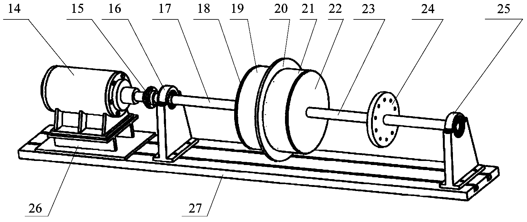
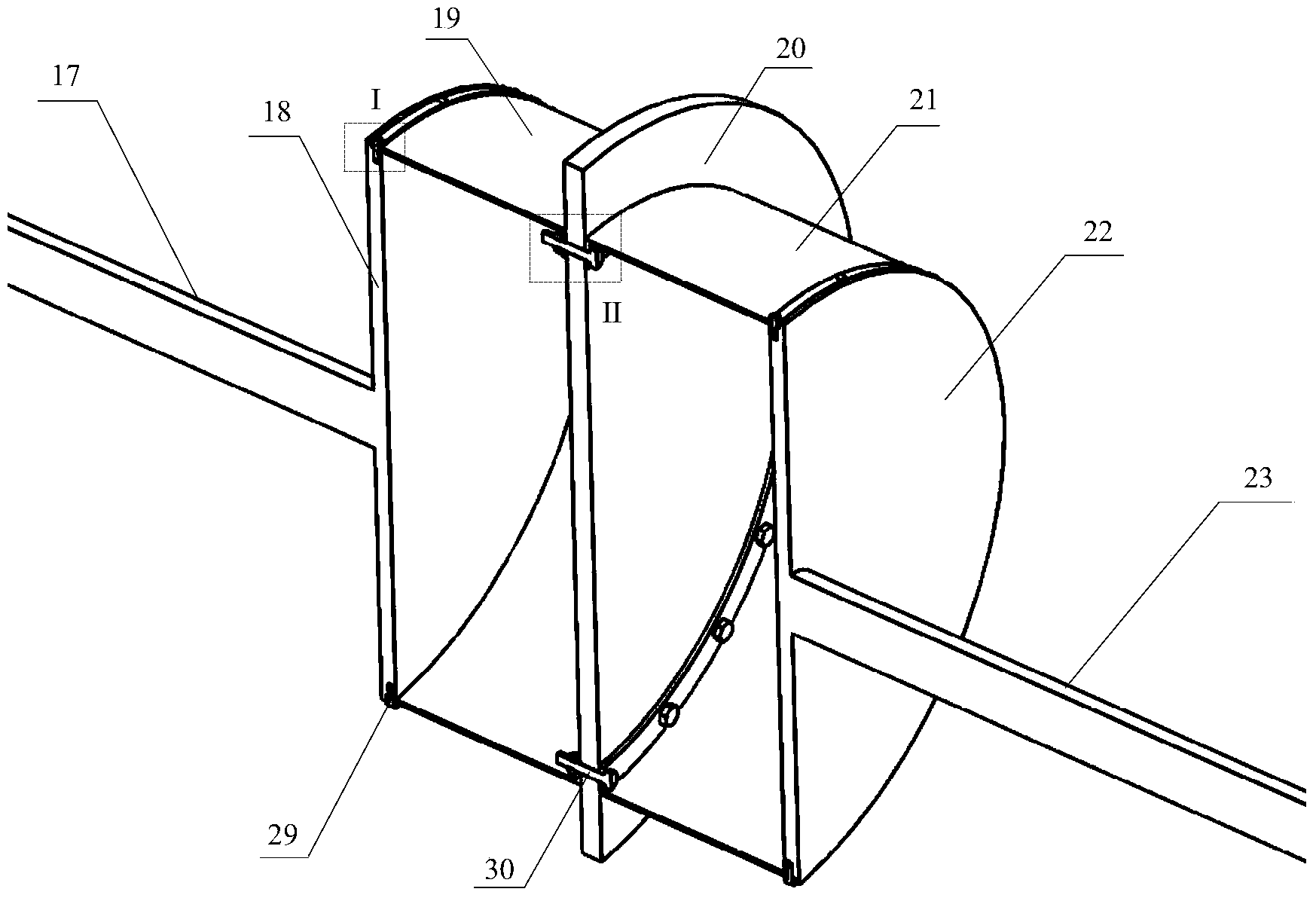
[0024] Such as figure 2 and image 3 As shown, the device is composed of a DC motor 14, an elastic coupling 15, a left bearing seat 16, a right bearing seat 25, a motor seat 26, a test bench base 27, and a disc-drum rotor; the left bearing seat 16, the right The side bearing seat 25 is arranged on the base 27 of the test bench, and a disc-drum rotor is installed between the left bearing seat 16 and the right bearing seat 25; a DC motor 14 is arranged on the outside of the left bearing seat 16, and the DC motor 14 passes through the motor seat. 26 is installed on the test bench base 27, links to each other with the left rotating shaft 17 of the disc-drum rotor stretching out the left side bearing seat 16 through the elastic coupling 15 and drives it to rotate.

[0025] The disc-d...


PUM


Abstract

The invention discloses an experimental device for simulating a bolt-connected disk-and-drum rotor of an aero-engine, belonging to the technical field of rotor dynamics. The device comprises two bearing seats installed on a test bench base, a disk-and-drum rotor is installed between the two bearing seats, a direct-current motor is arranged on the outer side of the left-side bearing seat, and the direct-current motor is installed on the test bench base through a motor seat and is connected with the disk-and-drum rotor through an elastic coupling. The body of the device is the disk-and-drum rotor which is composed of four wheel disks, two drums and two rotating shafts. The middle large-diameter wheel disk is connected with the drums on the two sides through bolts and inner flanges, the drums on the two sides are respectively in lap joint with the outer edges of the wheel disks on the outer sides, the radial outer sides are compressed tightly by two semi-circular clamps and are fixed by radial screws, the outer sides of the two wheel disks are fixedly connected with two circular-section solid rotating shafts, and the right-end rotating shaft is equipped with one wheel disk. The experimental device can be used for studying the dynamic characteristics of the disk-and-drum rotor and the transmission of vibration load in the disk-and-drum rotor.

Description

technical field [0001] The invention belongs to the technical field of rotor dynamics, in particular to an experimental device for simulating a bolt-connected disk-drum rotor of an aeroengine. Background technique [0002] Due to the advantages of good bending rigidity of the drum rotor and good strength of the disc rotor, the disc-drum rotor structure is widely used in aero-engines. The disc-drum rotor consists of discs, drums and shafts, and the discs and drums at all levels are connected by bolts or welded together. Such as figure 1 The disc-drum rotor in the fan section of a certain type of aero-engine shown is composed of a first-stage disc 1, a first-stage drum 2, a second-stage disc 3, a second-stage drum 5, and a third-stage disc 6. The first-stage drum 2, The secondary drum 5 is a thin-walled short cylindrical shell structure, which connects the primary wheel 1, the secondary wheel 3, and the third wheel 6 to transmit torque; the primary wheel 1 and the primary dr...

Claims


Application Information

Patent Timeline
IPC IPC(8): G01M15/00G01M13/02
Inventor 秦朝烨褚福磊李峥
Owner TSINGHUA UNIV
Why Eureka
Try Eureka