Design Method of Vibration Reduction for Suction and Discharge Pipeline of Rotary Compressor

A design method and compressor technology, applied to mechanical equipment, rotary piston type/oscillating piston type pump components, machines/engines, etc., can solve pipeline refrigeration system vibration, pipeline fatigue damage, long pipeline design cycle To achieve the effect of vibration reduction design and reduce the transmission of vibration

Active Publication Date: 2020-01-10
四川长虹空调有限公司
View PDF4 Cites 0 Cited by
  • Summary
  • Abstract
  • Description
  • Claims
  • Application Information

AI Technical Summary

Problems solved by technology

[0002] The structure of the rolling rotor compressor mainly includes motor rotors and stators, cylinders, rolling pistons, bearings, liquid reservoirs, and compressor housings. Since the rotating shaft of the compressor is an eccentric design structure, the unbalanced inertial force of the rotor when rotating It is easy to generate vibration, especially when the compressor is running at low frequency, which will cause vibration of the pipeline refrigeration system, lead to pipeline fatigue damage, and reduce product comfort and reliability
The vibration of the compressor piping system depends on the vibration characteristics of the compressor body and the inherent properties of the matching piping, and the vibration of the compressor vibration source has the greatest impact on the system vibration. At present, most of the design of the compressor piping in the industry Relying on the experience of the designer and repeated rectifications through experiments can reach the enterprise standard, resulting in long pipeline design cycle and high cost
However, the prior art does not provide an effective damping design method for the rolling rotor compressor pipeline

Method used


Image

  • Design Method of Vibration Reduction for Suction and Discharge Pipeline of Rotary Compressor
  • Design Method of Vibration Reduction for Suction and Discharge Pipeline of Rotary Compressor
  • Design Method of Vibration Reduction for Suction and Discharge Pipeline of Rotary Compressor

Examples


Embodiment Construction

[0020] Hereinafter, the present invention will be further described in detail with reference to the accompanying drawings of the specification, and specific implementation manners will be given.

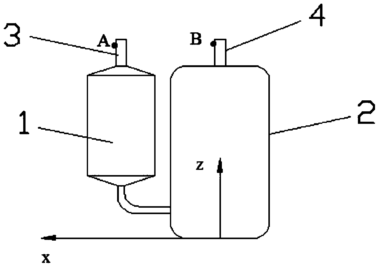
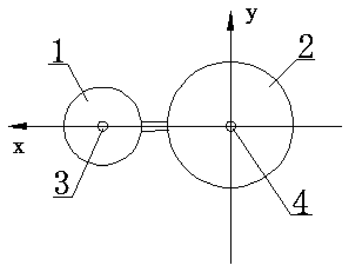
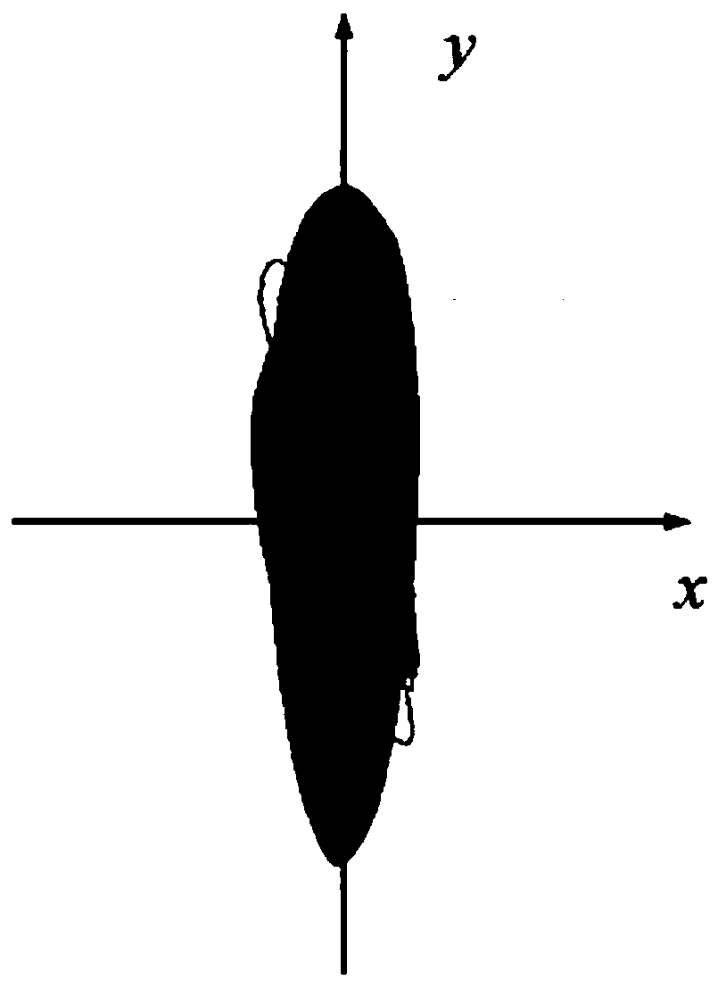
[0021] Such as Figure 1-5 As shown, the design method for damping vibration of the suction and exhaust pipelines of a rotor compressor includes:

[0022] a. Design a vibration test system according to the suction and discharge pipelines of the rotor compressor. The rotor compressor includes a connected liquid storage tank 1 and a compressor rigid body 2. The top center of the liquid storage tank 1 is provided with a suction port 3, the compressor rigid body 2 The top center is equipped with an exhaust port 4. The rotor compressor is also connected with refrigeration equipment through pipelines. The refrigeration equipment is used to control the pressure conditions of the suction and discharge of the rotor compressor; the vibration test system includes a frequency conversion controller an...


PUM


Abstract

The invention relates to a rotor type compressor air suction and exhaust pipeline vibration reduction design method and a vibration reduction system. The method comprises the following steps that a, avibration test system is designed according to an air suction and exhaust pipeline of a rotor type compressor; b, an air suction and exhaust opening connecting line of the rotor type compressor is used as an X direction; a direction vertical to the air suction and exhaust opening connecting line in the horizontal plane is used as a Y direction; c, a vibration sensor is respectively arranged in test points A and B; d, a vibration track diagram is respectively drawn according to vibration time-domain signals of the air suction and exhaust opening of the rotor type compressor in the X and Y direction; e, the maximum vibration direction of the air suction and exhaust opening of the rotor type compressor is obtained according to the vibration track diagrams of the air suction and exhaust opening of the rotor type compressor. Compared with the prior art, the method and the system have the advantages that the vibration transfer of the rotor type compressor is reduced to the greatest degree;the vibration reduction design is realized from the theory.

Description

Technical field [0001] The invention relates to a vibration reduction design of an air conditioner compressor, in particular to a vibration reduction design method of a suction and discharge pipeline of a rotor type compressor. Background technique [0002] The structure of the rolling rotor compressor mainly includes the motor rotor and stator, cylinder, rolling piston, bearing, accumulator and compressor housing and other components. Since the compressor shaft is an eccentric design structure, the rotor's unbalanced inertial force during rotation Vibration is easy to occur, especially when the compressor is running at low frequency, which can cause vibration of the pipeline refrigeration system, lead to pipeline fatigue damage, and reduce product comfort and reliability. The vibration of the compressor piping system depends on the vibration characteristics of the compressor body and the inherent properties of the matching piping. The vibration of the compressor vibration source...

Claims


Application Information

Patent Timeline
Patent Type & Authority Patents(China)
IPC IPC(8): F04C29/12F04C28/00F04C28/28
CPCF04C28/00F04C28/28F04C29/12F04C2270/125F04C2270/86
Inventor 邓培生李越峰董维夏培均
Owner 四川长虹空调有限公司
Why Eureka
Try Eureka