
Efficient measurement element, device and method for integrated gear errors

An overall error, measuring element technology, applied in the fields of mechanical transmission, precision testing technology and instruments, can solve the problems of small measuring range, non-uniform end face tooth profile, manufacturing difficulty of measuring worm, etc., so as to overcome manufacturing difficulties and shorten measuring time. Effect

Active Publication Date: 2014-04-09
BEIJING UNIV OF TECH
View PDF5 Cites 7 Cited by
  • Summary
  • Abstract
  • Description
  • Claims
  • Application Information

AI Technical Summary

Problems solved by technology

Simultaneously, the present invention no longer uses the measuring worm as the standard measuring element, overcomes the problem that the high-precision measuring worm in the traditional worm-type overall error measuring instrument is difficult to manufacture, and overcomes the problem that the worm-type overall error measuring instrument measures the helical gear. What is most important is the problem that the normal meshing tooth shape is not uniform with the internationally customary end face tooth shape, and the shortcoming of the small measurement range of the worm gear overall error measuring instrument
[0009] The present invention aims at the defects of the existing gear overall error measurement method, and carries out principle innovation. The basic idea is: the gear overall error theory has been using the jumping tooth measuring element since the birth of the gear overall error theory. The reason is that the overall error measurement principle requires the measuring element and the measured gear The degree of coincidence between them during the meshing measurement process must be less than 1, so that it is possible to distinguish which tooth surface produces the motion error

Method used


Image

  • Efficient measurement element, device and method for integrated gear errors
  • Efficient measurement element, device and method for integrated gear errors
  • Efficient measurement element, device and method for integrated gear errors

Examples


Embodiment Construction

[0041] Below in conjunction with accompanying drawing, present embodiment is described further:

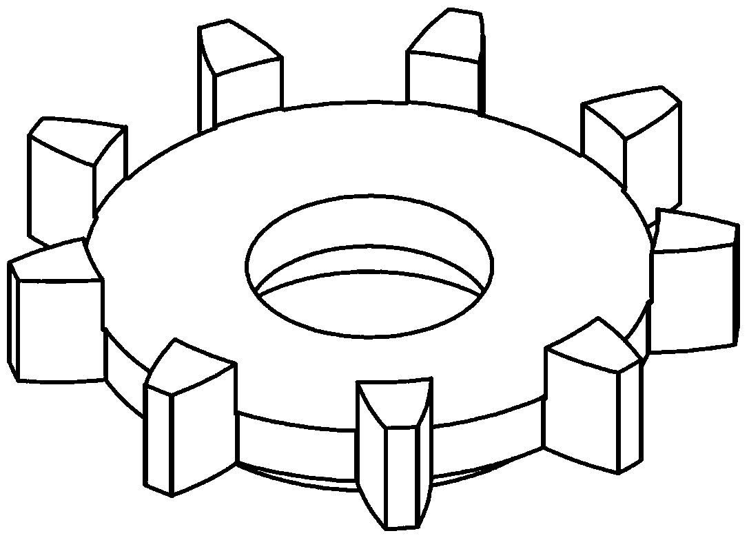
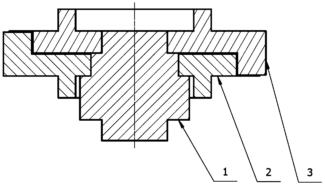
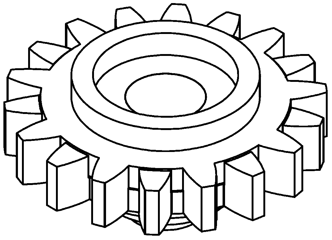
[0042] This embodiment designs and manufactures a combined measuring element composed of two half gears and a high-efficiency overall error measuring device using the combined measuring element, and illustrates the measurement method using the high-efficiency overall error measuring device. In this embodiment, the rolling point scanning measurement of all the teeth of the gear under test is realized by combining the measuring elements, and the angular displacement signal generated by the combined measuring element and the gear under test during the transmission process is converted into an electrical signal through a circular grating, and the data is collected The circuit is input into the computer, and after analysis and calculation and data processing, the overall error, individual error and comprehensive error of the tested gear can be obtained according to the international and...


PUM


Abstract

The invention provides an efficient measurement element, device and method for integrated gear errors, and belongs to the field of the precision testing technology and instrument and the mechanical transmission technology. The combined standard element is composed of two measurement half-gears in a combined mode, wherein the two measurement half-gears are installed coaxially, can rotate independently and are respectively provided with a circular grating, and the independent angle position of each measurement half-gear can be measured; meanwhile, the device and method using the element for conducting specific gear measurement are provided. According to the efficient measurement element, device and method, the defect that one-side tooth surface measurement can be completed only after a measured gear rotates by two or more circles during integrated gear error measurement at present is overcome, one-side tooth surface measurement can be completed only after the measured gear rotates by one circle, and in the measurement process, under the condition that the measured gear rotates at the same speed, measurement time can be shortened by more than one time after the measurement method is adopted.

Description

technical field [0001] The invention relates to a combined measuring element, a measuring device and a measuring method for efficiently measuring the overall error of a gear, and belongs to the technical fields of precision testing technology, instruments and mechanical transmission. Background technique [0002] The measurement method of the overall gear error was first initiated by Chinese scientists and technicians in the early 1970s. This method can extract the individual error and comprehensive error information of the gear from the overall error curve of the gear. The emergence of this method solves the problem of how to quickly obtain all error information of gears on one instrument in the field of gear measurement. After more than 30 years of improvement and promotion, the overall gear error measurement method has developed into a motion geometry measurement method for transmission components in my country. The basic idea is to use the measured object as a rigid func...

Claims


Application Information

Patent Timeline
IPC IPC(8): G01M13/02
Inventor 石照耀王笑一
Owner BEIJING UNIV OF TECH
Learn More