Yarn unwinding system

An unwinding and yarn technology, applied in textiles and papermaking, weft knitting, knitting and other directions, can solve the problems of large variation in unwinding resistance, uneven tension, complex structure, etc. Consistent effect around conditions

Inactive Publication Date: 2015-07-01
NANTONG TEXTILE INST OF SOOCHOW UNIV
View PDF12 Cites 0 Cited by
  • Summary
  • Abstract
  • Description
  • Claims
  • Application Information

AI Technical Summary

Problems solved by technology

Therefore, the factors that cause a significant impact on the unwinding process of metal fibers will not have a significant impact on the unwinding during traditional textile fiber weaving. Accordingly, there is no unwinding system specifically for metal fiber yarns in the prior art.
[0005] When using a traditional circular weft machine to unwind the metal fiber yarn, there will be the following problems: when the yarn is unwound along the horizontal direction, it will rotate around the bobbin to form a balloon, and the self-weight of the yarn has an impact on the shape of the balloon. A certain influence causes the yarn to rub against the surface of the bobbin, and when the yarn is on the center line of the shaft, the length of the rubbing yarn section on the bobbin surface and the unwinding conditions are inconsistent, resulting in uneven tension and large changes in unwinding resistance
However, these existing improved technologies not only have complex structures and increase equipment costs, but also do not fundamentally change the horizontal unwinding of the outer creel of the circular weft machine to the vertical unwinding that meets the characteristics of pure metal yarns, which is not applicable Unwinding characteristics for pure metallic yarns

Method used


Image

  • Yarn unwinding system

Examples


Embodiment Construction

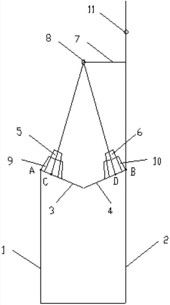
[0019] The outer creel of the traditional circular weft machine is horizontal unwinding. When the traditional circular weft machine is used to unwind the metal fiber yarn, there will be the following problems: when the yarn is unwound along the horizontal direction, it will rotate around the bobbin to form Balloon, the influence of the weight of the yarn on the shape of the balloon is far greater than that of conventional textile yarns, causing friction between the yarn and the surface of the bobbin, and the friction between the yarn and the surface of the bobbin when the yarn is on the centerline of the shaft and down The length and unwinding conditions are inconsistent, resulting in uneven tension and large changes in unwinding resistance.

[0020] In view of the above-mentioned problems existing in the prior art, it is necessary to design a yarn unwinding system specially suitable for pure metal yarn unwinding conditions.

[0021] The invention discloses a yarn unwinding sy...


PUM


Abstract

Provided is a yarn unwinding system. The yarn unwinding system comprises a first creel vertical rod, a second creel vertical rod, a first bobbin supporting frame, a second bobbin supporting frame, a first bobbin base, a second bobbin base and a first thread eye, wherein the first bobbin supporting frame and the second bobbin supporting frame are arranged in the mode that the included angle between the first bobbin supporting frame and the first creel vertical rod and the included angle between the second bobbin supporting frame and the second creel vertical rod are acute angles and are equal, the first bobbin base is perpendicularly arranged on the top of the first bobbin supporting frame, the second bobbin base is perpendicularly arranged on the top of the second bobbin supporting frame, bobbins are arranged on the first bobbin base and the second bobbin base in a sleeved mode respectively, the first thread eye is formed in the middle of the portion above the position between the first bobbin base and the second bobbin base, the center line of the first thread eye, the center line of the first bobbin base and the center line of the corresponding bobbin are arranged on the same straight line, and the center line of the first thread eye, the center line of the second bobbin base and the center line of the corresponding bobbin are arranged on the same straight line. Therefore, horizontal unwinding of a creel arranged outside a traditional circular knitting machine is changed into perpendicular unwinding, when unwinding is carried out on bobbins, unwinding is carried out on each bobbin along the center line of a bobbin shaft, the portions, in the circumferential direction, of the bobbins are the same in unwinding condition, and unwinding resistance on the portions, in the circumferential direction, of the bobbins cannot fluctuate.

Description

technical field [0001] The invention relates to the technical field of textiles, in particular to a yarn unwinding system. Background technique [0002] Pure metal fiber fabrics represented by stainless steel are being more and more widely used in the field of industrial textiles because of their high strength, corrosion resistance, high temperature resistance, cutting resistance, and good three-dimensional bending when covering the surface of objects. Especially in recent years, the fineness of metal fibers can reach the micron level, and the textile processing performance of fibers has been further optimized, making textile processing of pure metal fibers possible. However, due to the performance characteristics that are obviously different from traditional textile fibers, there are still various problems to be solved in the textile processing of pure metal fibers, especially the knitting process that needs to bend the yarn into loops during the processing is more difficul...

Claims


Application Information

Patent Timeline
Patent Type & Authority Patents(China)
IPC IPC(8): D04B15/40
Inventor 孙玉钗程中浩
Owner NANTONG TEXTILE INST OF SOOCHOW UNIV
Why Eureka
Try Eureka