
Split type girder moving crane

A crane and split technology, which is applied in the field of split beam-moving cranes, can solve problems such as limiting the hoisting range of the crane, and achieve the effects of increasing the hoisting range, reducing the overall weight, and saving production costs

Inactive Publication Date: 2014-04-09
ZHEJIANG ZHONGJIAN ROAD & BRIDGE EQUIP
View PDF7 Cites 5 Cited by
  • Summary
  • Abstract
  • Description
  • Claims
  • Application Information

AI Technical Summary

Problems solved by technology

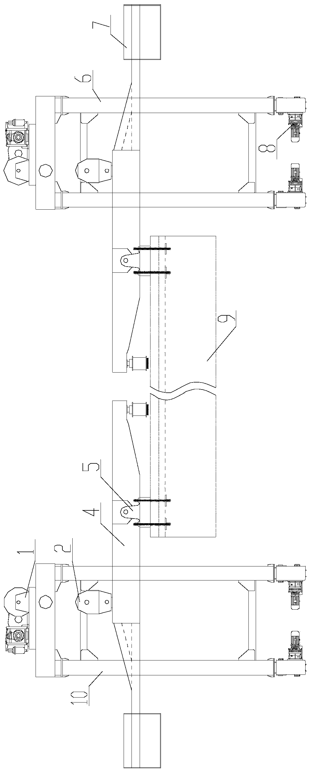
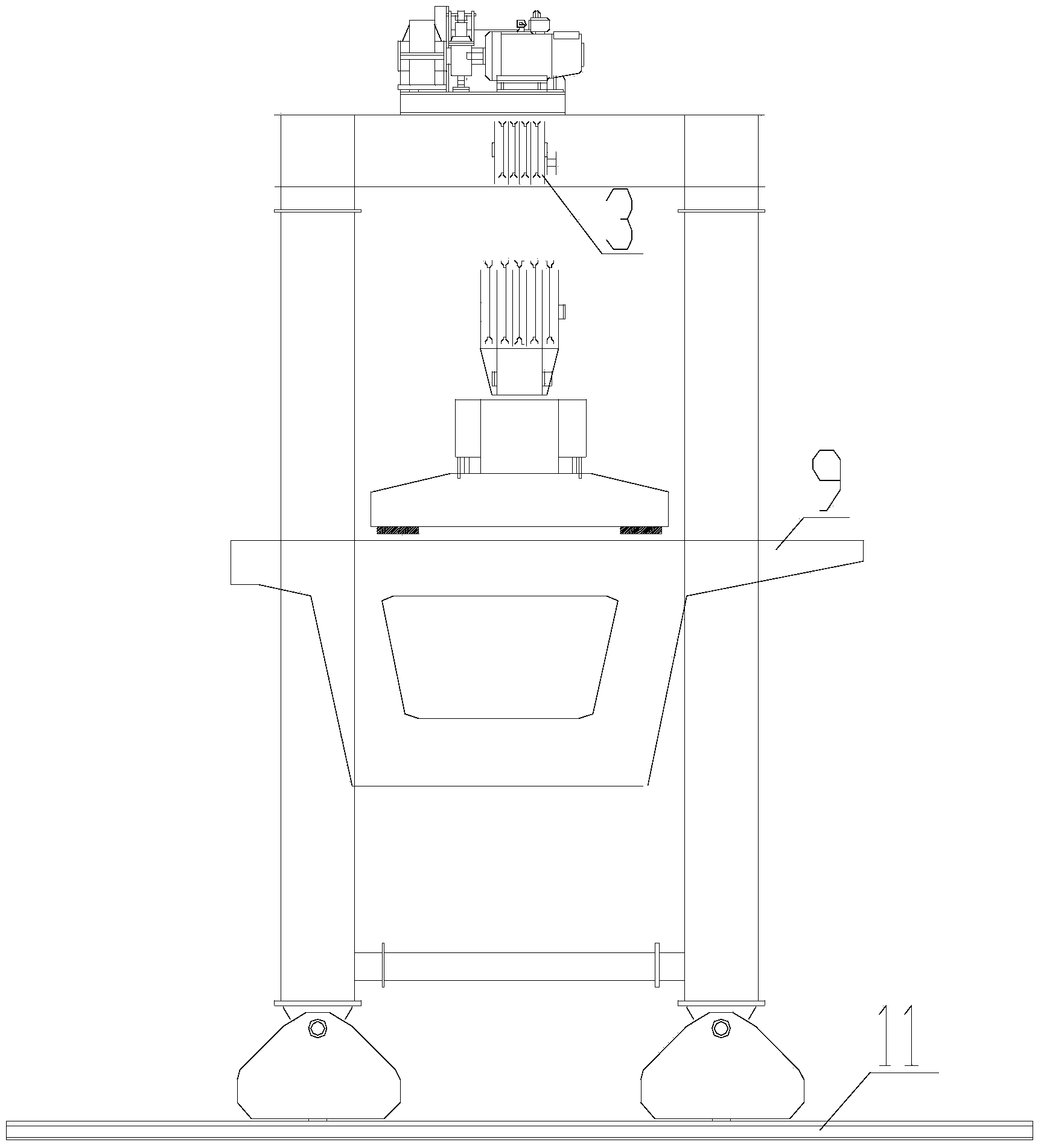
In the process of bridge erection, the beam and slab components need to be hoisted to the designated position by the crane for installation, but now the cranes are all conjoined structures, and the beams are connected above the crane, so the width of the crane cannot be changed according to the site environment, which is severely limited Lifting scope of the crane

Method used


Image

  • Split type girder moving crane
  • Split type girder moving crane

Examples


Embodiment

[0013] Embodiment: split type beam moving crane, such as figure 1 with figure 2 As shown, it includes a left crane frame and a right crane frame, and the top of the left crane frame and the right crane frame is provided with a winch, and a fixed pulley block is arranged on the winch, and the fixed pulley block is connected with the movable pulley block, and the movable pulley block It is connected with the pole of the hanging beam; the bottom of the frame of the left crane and the frame of the right crane is equipped with a traveling mechanism to control the movement of the split beam moving crane along the track; the pole of the hanging beam is equipped with a counterweight for balancing the hanging beam A shoulder pole; a spreader is arranged on the pole of the hanging beam.

[0014] When working, the bridge components are first fixed on the suspension girder shoulder pole by the spreader, and after the bridge components are anchored, the winches on the left crane frame an...


PUM


Abstract

The invention relates to a split type girder moving crane. The split type girder moving crane comprises a left crane frame and a right crane frame, wherein the tops of the left crane frame and the right crane frame are provided with winding engines, each winding engine is provided with a fixed pulley group, each fixed pulley group is connected with a movable pulley group, and each movable pulley group is connected with a suspension girder shoulder pole; and the bottoms of the left crane frame and the right crane frame are provided with running mechanisms. During working, a bridge component is firstly fixed on the suspension girder shoulder pole through a hanger, then the winding engines on the left crane frame and the right crane frame are started at the same time after the bridge component is anchored so that the bridge component is raised to an appointed height, then the running mechanisms are started to drive the left crane frame and the right crane frame to move front and back along rails so that the split type girder moving crane moves to an appointed position, then the winding engines are started, and the bridge component is placed at a specific position for installation.

Description

technical field [0001] The invention belongs to the technical field of bridge lifting equipment, and in particular relates to a split beam-moving crane suitable for bridge construction. Background technique [0002] With the needs of my country's economic proposals and the rapid development of China's expressways, there are more and more bridge constructions. As large-scale special equipment in construction, highway bridge erecting machines have become indispensable key equipment in expressway bridge construction. In the process of bridge erection, the beam and slab components need to be hoisted to the designated position by the crane for installation, but now the cranes are all conjoined structures, and the beams are connected above the crane, so the width of the crane cannot be changed according to the site environment, which is severely limited Lifting range of the crane. Contents of the invention [0003] The present invention mainly solves the above-mentioned technic...

Claims


Application Information

Patent Timeline
IPC IPC(8): B66C11/16B66C6/00B66C11/14
Inventor 赵建华师韵童国柱
Owner ZHEJIANG ZHONGJIAN ROAD & BRIDGE EQUIP
Learn More