
A single-input and double-output pulse width modulation signal generating circuit

A pulse width modulated signal, single-input and double-output technology, applied in the field of switching device drive control, can solve problems such as inability to meet usage requirements, increased DSP cost, occupation, etc., to avoid the risk of direct connection of the same bridge arm, improve reliability, The effect of flexible settings

Active Publication Date: 2016-05-25
SUZHOU INOSA UNITED POWER SYST CO LTD
View PDF5 Cites 0 Cited by
  • Summary
  • Abstract
  • Description
  • Claims
  • Application Information

AI Technical Summary

Problems solved by technology

Taking the three-phase AC motor as an example, the current domestic motor control scheme mainly uses the DSP produced by TI manufacturer as the main control chip, configures the 6-way PWM peripheral of the chip through software to generate modulation waves, and then controls the switching elements to complete the electronic commutation At the same time, the dead time is also completed through the configuration register. Although the method of configuring the PWM peripheral of the DSP through software is relatively simple in control, it needs to occupy 6 PWM port outputs. For some applications that require a large PWM port, Such a design obviously cannot meet the needs of use. For example, in the case where multiple analog outputs are required while controlling the motor, the best way for analog output is to reflect the output through the pulse width change of the PWM port, and the DSP with more PWM ports Its cost will also increase significantly

Method used


Image

  • A single-input and double-output pulse width modulation signal generating circuit
  • A single-input and double-output pulse width modulation signal generating circuit

Examples


Embodiment Construction

[0020] In order to have a clearer understanding of the technical features, purposes and effects of the present invention, the specific implementation manners of the present invention will now be described in detail with reference to the accompanying drawings.

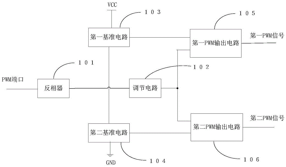
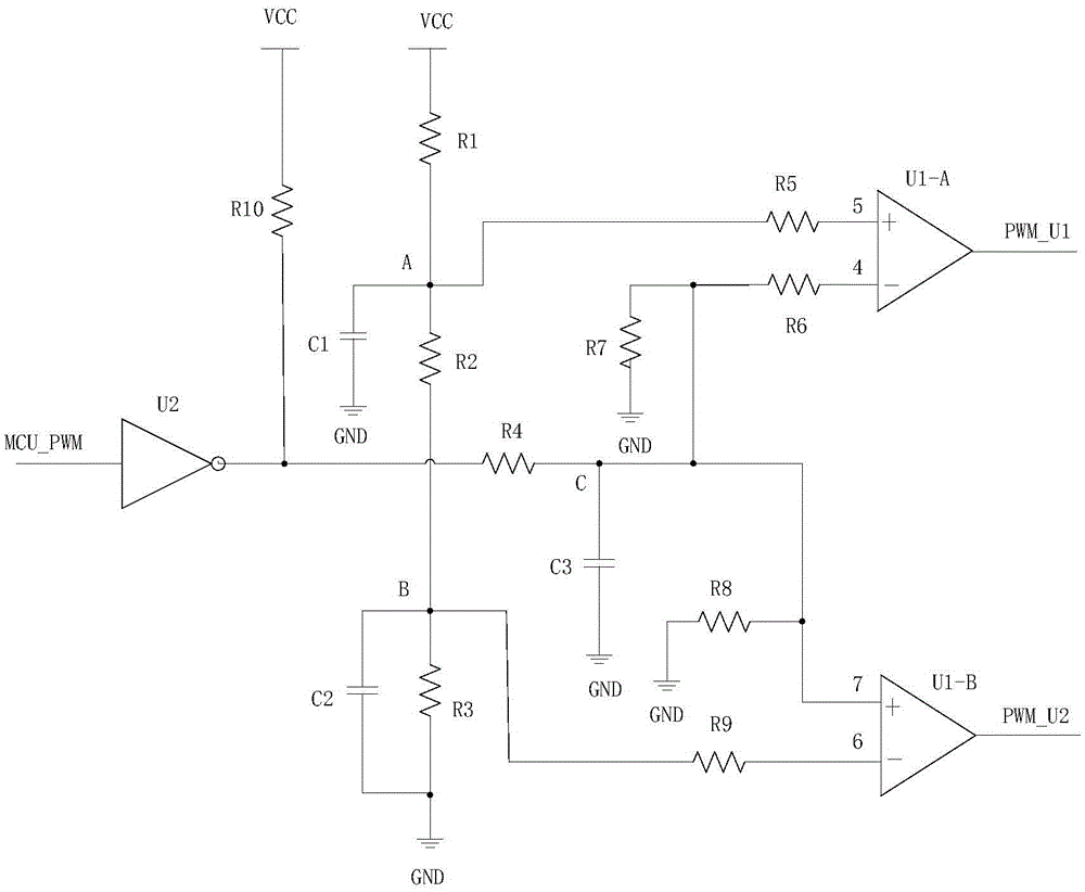
[0021] figure 1 It is a functional block diagram of a single-input and double-output pulse width modulation signal generation circuit of the present invention, including an inverter 101 connected to the PWM port of the microcontroller, an adjustment circuit 102 electrically connected to the inverter 101, and an adjustment circuit 102 connected to the inverter. The first PWM output circuit 105 electrically connected to the circuit 102 and the first reference circuit 103, the second PWM output circuit 106 electrically connected to the regulating circuit 102 and the second reference circuit 104, one end of the first reference circuit 103 is connected to the external power supply VCC is connected, and the other end of the f...


PUM


Abstract

The invention discloses a single-input double-output pulse width modulation (PWM) signal producing circuit, comprising a phase inverter (101), a regulating circuit (102), a first PWM output circuit (105) and a second PWM output circuit (106), wherein the phase inverter (101) is connected with a PWM port of a microcontroller; the regulating circuit (102) is electrically connected with the phase inverter (101); the first PWM output circuit (105) is electrically connected with the regulating circuit (102) and a first reference circuit (103); the second PWM output circuit (106) is connected with the regulating circuit (102) and a second reference circuit (104); one end of the first reference circuit (103) is connected with an external power source; the other end of the first reference circuit (103) is grounded through the second reference circuit (104). The single-input double-output pulse width modulation signal producing circuit has the beneficial effect that the microcontroller only uses one PWM port to control two switch elements of a same bridge arm and produce dead-time, so that the PWM port of the microcontroller can be effectively saved.

Description

technical field [0001] The invention relates to the technical field of drive control of switching devices, and more specifically, to a single-input and double-output pulse width modulation signal generating circuit. Background technique [0002] In the fields of household appliances, industrial control, power supply, etc., it is often necessary to control multiple switching devices at the same time, so multiple PWM (PulseWidthModulation, pulse width modulation) ports are required. When a single microcontroller is used for control, the PWM ports are not enough. Usually The method of increasing the number of microcontrollers is to increase the number of PWM ports. This method not only needs to solve the communication problem between multiple microcontrollers, but also increases the complexity of the system control and also increases the cost. [0003] In the prior art, the microcontroller usually outputs two complementary control signals to control the two switching elements o...

Claims


Application Information

Patent Timeline
Patent Type & Authority Patents(China)
IPC IPC(8): H03K7/08H02P6/14
Inventor 汪顺军潘波杨睿诚张昊梁松波张超
Owner SUZHOU INOSA UNITED POWER SYST CO LTD
Learn More