
Auxiliary tool for single-person night electric power operation

A technology of electric power work and auxiliary tools, which is applied in the direction of overhead lines/cable equipment, etc., and can solve the problem that two hands are not enough

Inactive Publication Date: 2014-01-01
STATE GRID CORP OF CHINA +1
View PDF6 Cites 0 Cited by
  • Summary
  • Abstract
  • Description
  • Claims
  • Application Information

AI Technical Summary

Problems solved by technology

[0004] The purpose of the present invention is to address the deficiencies of the prior art, thereby providing a single-person electric work auxiliary tool at night that can be used as an auxiliary arm for electric workers and effectively solves the problem that two hands are not enough when a single person works at night

Method used


Image

  • Auxiliary tool for single-person night electric power operation

Examples


Embodiment 1

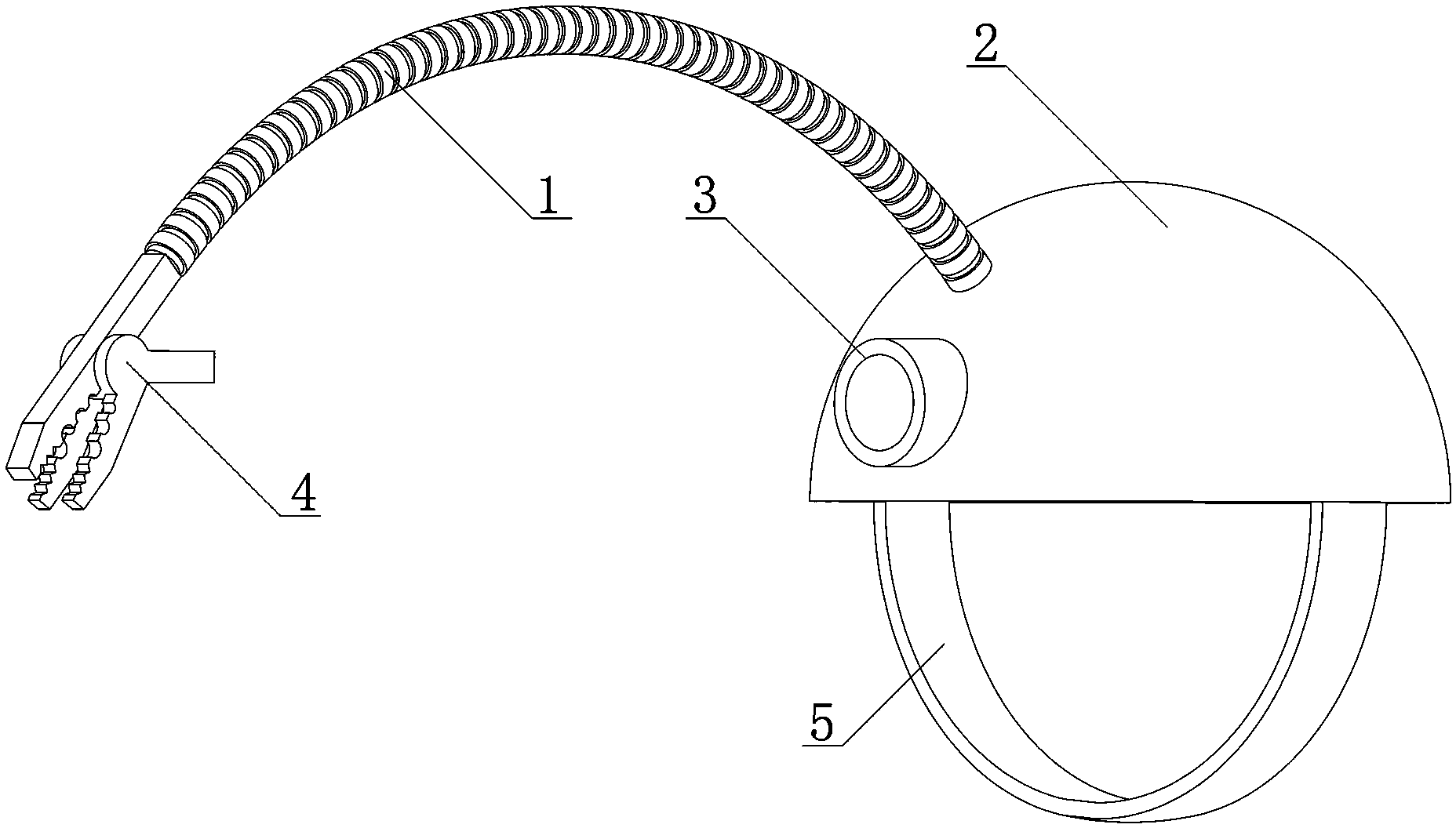
[0016] Such as figure 1 As shown, a single-person electric power operation auxiliary tool at night includes an auxiliary arm 1 and fixing caps 2 and tools respectively installed at both ends of the auxiliary arm 1, the fixing cap 2 is provided with a lamp 3, and the tool is arranged on on the light path of the lamp 3 . When in use, the electric worker puts the fixed cap 2 on his head, turns on the light 3 and irradiates the light 3 to the maintenance site of the electric equipment, and then adjusts the auxiliary arm 1 as required so that the tool is located The light path of the lamp 3 corresponds to the maintenance site of the electric equipment, so the auxiliary arm 1 is equivalent to the third hand of the electric worker, and participates in the maintenance of the electric equipment together with both hands of the electric worker. The advantage of setting the tool on the light path of the lamp 3 is that when the electric worker adjusts the lighting position by turning his ...

Embodiment 2

[0018] The difference between embodiment 2 and embodiment 1 is that the auxiliary arm 1 is a metal shaped hose with an insulating jacket. The metal shaped hose can be bent into a certain shape arbitrarily in the three-dimensional space and can maintain its shape, so the use of the metal shaped hose can make the tools on the auxiliary arm 1 accurately correspond to the light path of the lamp 3, allowing electric workers It can be seen clearly, and the support force of the metal shaped hose is used to bear the limited structural strength, which is convenient for electric workers to construct accurately.

Embodiment 3

[0020] The difference between embodiment 3 and embodiment 2 is that: the fixing cap 2 is provided with a through hole, and the auxiliary arm 1 is screwed into the through hole. Because the auxiliary arm 1 is located on the outside of the fixed cap 2, it is not easy to accommodate when not in use at ordinary times, so the auxiliary arm 1 can be screwed into the through hole when it is not in use. 1, and then screwed into the other side of the through hole, that is, installed on the inside of the fixed cap 2, and then the auxiliary arm 1 is bent and coiled in the fixed cap 2, so that the space occupied by the overall structure becomes smaller. Small and easy to store.


PUM


Abstract

The invention provides an auxiliary tool for single-person night electric power operation. The auxiliary tool comprises an auxiliary arm, a fixing cap and a tool body. The fixing cap and the tool body are arranged at the two ends of the auxiliary arm respectively, a lamp is arranged on the fixing cap, and the tool body is arranged on the light path of the lamp. The fixing cap is placed on the head of an electrical worker, and the auxiliary arm is adjusted according to needs, so that the tool body is located on the light path of the lamp and corresponds to the maintenance position of electrical equipment. The auxiliary arm is used as the third hand of the electrical worker, and is involved in maintenance of the electrical equipment together with the hands of the electrical worker. The auxiliary tool for single-person night electric power operation can be used as the auxiliary arm for the electrical worker, and effectively solves the problem that two hands are insufficient for single-person night operation.

Description

technical field [0001] The invention relates to an electric power work tool, in particular to a single-person electric power work auxiliary tool for night electric power work. Background technique [0002] Electricity work at night is dark, and lights are needed to work. And electric worker can run into the situation that has only one person's work in electric work at night, carries out high-altitude work etc. as pedaling electric pole, and in this type of situation, electric worker needs one person to complete this electric work. Due to the complexity of electrical equipment, some equipment failures are not easy to be completed by a single person. Often, electric workers feel that two hands are not enough and must be completed with help. In fact, they can only be operated by one person, and the night light Not good, it has brought great inconvenience to the work of electric workers. [0003] In order to solve the above existing problems, people have been seeking an ideal ...

Claims


Application Information

Patent Timeline
IPC IPC(8): H02G1/02
Inventor 熊炬李梅汤玉丽
Owner STATE GRID CORP OF CHINA
Learn More