Rotary separation conveyor

A conveyor and rotary technology, applied in the field of rotary separation conveyors, can solve the problems of reducing the service life of the equipment, polluting the air, short conveying width, etc., and achieving the effect of increasing the conveying volume, reducing the moisture content of the garbage and reducing the friction force.

Active Publication Date: 2014-04-02
LANSHEN GRP CORP LTD +1
View PDF7 Cites 1 Cited by
  • Summary
  • Abstract
  • Description
  • Claims
  • Application Information

AI Technical Summary

Problems solved by technology

At present, the commonly used garbage and dirt conveying equipment in this industry mainly include belt conveyors and screw conveyors. These conveyors have their own advantages and disadvantages. The conveying volume of both is not large and the conveying width is short.
The dirt transported by the belt conveyor not only has a high water content, but also the dirt is exposed to the outside, resulting in an unpleasant smell in the air around the equipment and polluting the air; although the dirt is in a semi-closed state during the conveying process of the screw conveyor, the volume of the conveying body is small, and when encountering The working condition with a large volume of dirt will easily cause the conveying screw and gland to be stuck by the large volume of dirt, resulting in overload damage to the equipment and reducing the service life of the equipment

Method used


Image

  • Rotary separation conveyor
  • Rotary separation conveyor
  • Rotary separation conveyor

Examples


Embodiment Construction

[0022] The technical solution of the present invention will be described in detail below in conjunction with the accompanying drawings.

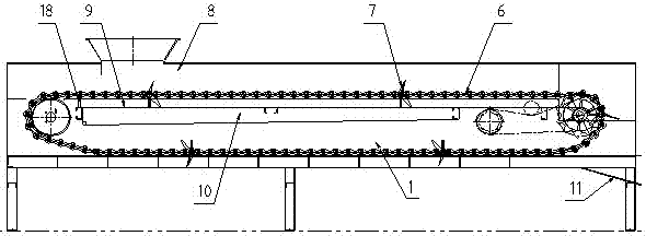
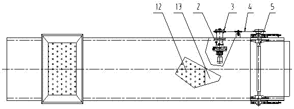
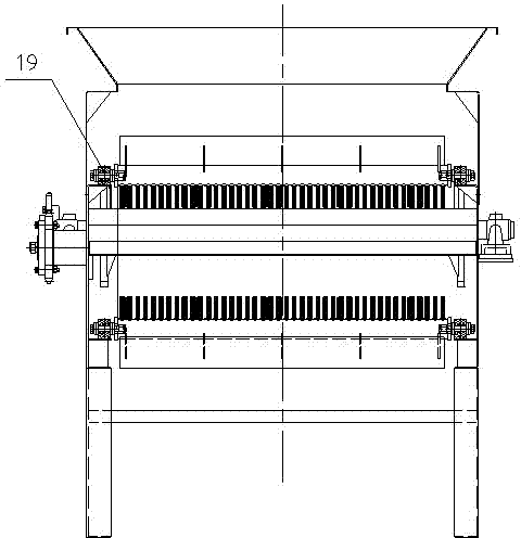
[0023] like figure 1 , figure 2 , image 3 and Figure 4 As shown, the rotary separation conveyor of the present invention includes a conveying frame 1, and a shaft-mounted geared motor 2 arranged inside the conveying frame 1, and a driving part 3 is connected to the output end of the geared motor 2, and the driving part 3. Connected with the transmission device 5 through the roller chain 4, the transmission device 5 drives the slag removal device 7 to run along the track through the transmission chain 6, and the dirt enters the conveying box through the material connection port of the odor-proof cover 8 and is discharged on the support On the plate 9, part of the water contained in the dirt enters the sump 10 through the holes of the supporting plate 9 due to gravity, and the sewage is transported to the relevant drainage system thr...


PUM


Abstract

The invention relates to a rotary separation conveyor which comprises a residue fishing device, a transmission device, a conveying frame, a driving component, a water collection tank and an odor isolation cover. An axle-mounted speed reducer is mounted in the conveying frame, an output end of the speed reducer is connected with a driving chain wheel group, the driving chain wheel group is connected with the transmission device through a roller chain, the transmission device drives a driving chain passing a nylon roller to drive the residue fishing device to run, the residue fishing device is a spacer bar, a steel plate is welded on the upper portion of the spacer bar, harrow teeth are welded on the lower portion of the spacer bar, a garbage supporting plate is made of a bent stainless steel perforated steel plate, and the odor isolation cover is arranged outside the whole frame. By the aid of a novel rotary separation structure, the length and the width of the conveying frame are not strictly limited, conveying capacity is greatly improved, the running process is stable and low in noise, the supporting plate is made of the perforated steel plate, the water content of dirt can be greatly reduced, so that the dirt is more convenient to transport and treat, the whole conveyor is sealed, influence on peripheral air is less, and a control system is simple.

Description

technical field [0001] The invention belongs to a sewage treatment device, in particular to a rotary separation conveyor for grid slag and sewage treatment. Background technique [0002] The rotary separation conveyor is used for the separation and transportation of garbage and dirt. At present, the commonly used conveying equipment for garbage and dirt in this industry mainly includes belt conveyors and screw conveyors. Both of these conveyors have their own advantages and disadvantages. The conveying volume of both is not large and the conveying width is short. The dirt transported by the belt conveyor not only has a high water content, but also the dirt is exposed to the outside, resulting in an unpleasant smell in the air around the equipment and polluting the air; although the dirt is in a semi-closed state during the conveying process of the screw conveyor, the volume of the conveying body is small, and when encountering The working condition with large volume of dirt...

Claims


Application Information

Patent Timeline
IPC IPC(8): B65G17/00B65G17/30B65G21/08
Inventor 高标余必升孙凯李双双刘晓娟李慧许荣军陈刻强胡啟祥
Owner LANSHEN GRP CORP LTD
Why Eureka
Try Eureka