Phase lock loop

A phase-locked loop and circuit technology, applied in the direction of electrical components, automatic power control, etc., can solve the problems affecting the performance of traditional phase-locked loop 1, output jitter, etc., to achieve the effect of reducing output jitter and improving performance

Inactive Publication Date: 2014-03-26
REALTEK SEMICON CORP
View PDF4 Cites 0 Cited by
  • Summary
  • Abstract
  • Description
  • Claims
  • Application Information

AI Technical Summary

Problems solved by technology

However, the series resistance R of the conventional PLL 1 s It is easy to generate noise and cause output jitter (Jitter), which in turn affects the performance of traditional PLL1

Method used


Image

  • Phase lock loop
  • Phase lock loop
  • Phase lock loop

Examples


no. 1 example

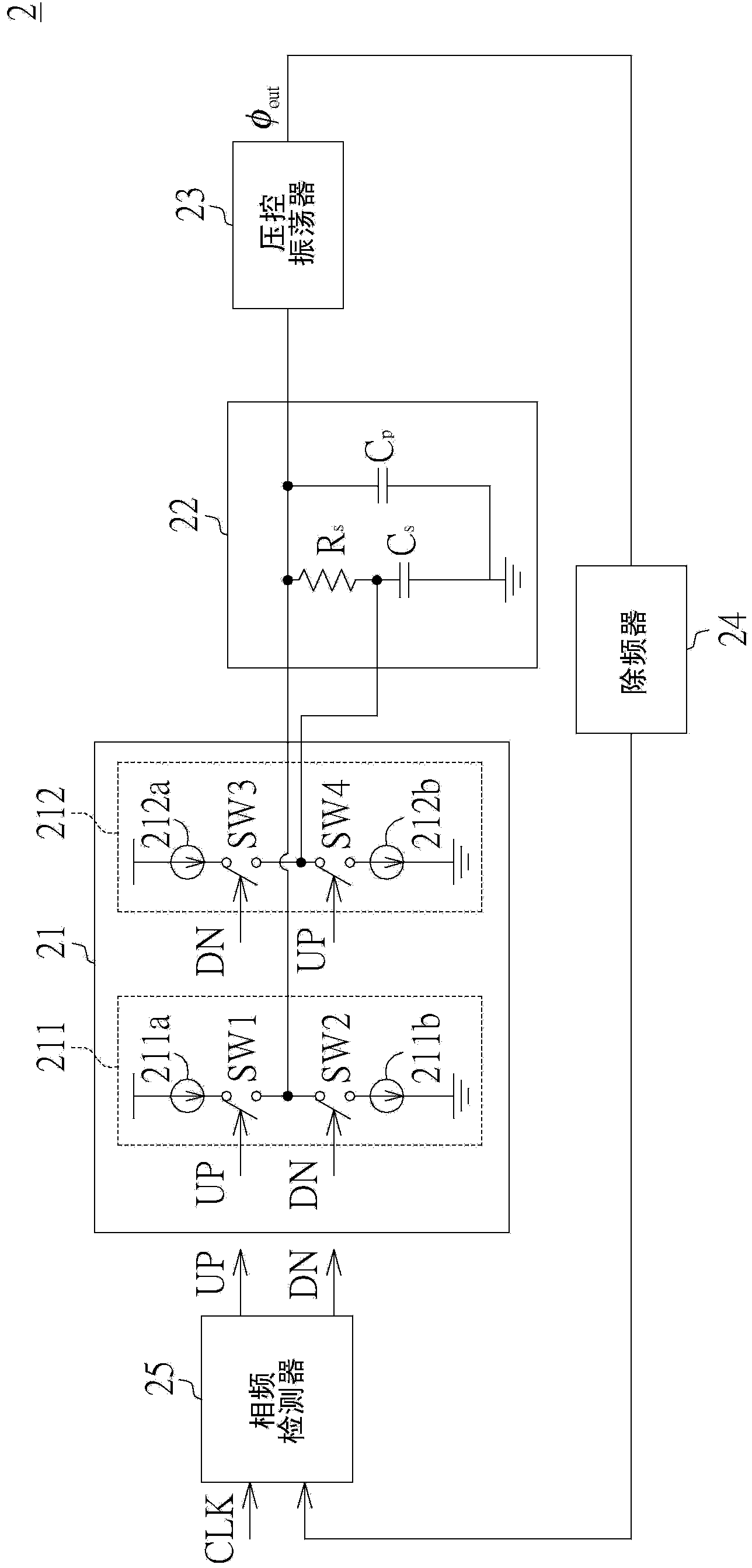
[0036] Please also refer to figure 1 and figure 2 , figure 2 is a schematic diagram of a phase lock loop (PLL) according to the first embodiment. The phase locked loop 2 includes a charge pump circuit 21 , a loop filter 22 , a voltage controlled oscillator 23 , a frequency divider 24 and a phase frequency detector (Phase Frequency Detector) 25 . The voltage controlled oscillator 23 generates an oscillation signal Φ according to the output of the loop filter 22 out ’, the phase frequency detector 25 according to the oscillation signal Φ out ’ and the clock signal CLK provide the switch signal UP and the switch signal DN.

[0037] The loop filter 22 includes a shunt capacitor C p ’, series resistance R s ’ and the series capacitor C s '. Series resistance R s ’ is electrically connected to the parallel capacitor C p ’ at one end. Series capacitance C s ’ is electrically connected to the series resistor R s ’, while the series capacitor C s ’ The other end is elec...

no. 2 example

[0058] Please refer to Figure 5 , Figure 5 is a schematic diagram of a phase-locked loop according to the second embodiment. The second embodiment differs from the first embodiment in that the PLL 3 uses a third-order loop filter 32 . The loop filter 32 divides the shunt capacitor C p ’, series resistance R s ’ and the series capacitor C s ’, also includes the resistor R 1 and capacitance C 1 . Resistance R 1 One end is coupled to the series resistor R s ’ at one end. Capacitance C 1 One end of the resistor R1 is coupled to the other end, and the other end of the capacitor C1 is coupled to the series capacitor C s ’ the other end. In addition, in other embodiments, the phase-locked loop may also use loop filters of other orders.


PUM


Abstract

The invention discloses a phase lock loop which comprises a loop filter and a charge pump circuit. The loop filter comprises a parallel capacitor, a series resistor and a series capacitor, wherein one end of the series resistor is electrically connected with one end of the parallel capacitor, one end of the series capacitor is electrically connected with the other end of the series resistor, and the other end of the series capacitor is electrically connected with the other end of the parallel capacitor; the charge pump circuit comprises a first charge pump and a second charge pump, wherein the first charge pump is electrically connected with one end of the series resistor, and the second charge pump is electrically connected with the other end of the series resistor. The phase lock loop provided by the invention can reduce the output jitter, thereby improving the efficiency of the phase lock loop.

Description

technical field [0001] The present invention relates to a loop, and in particular to a phase-locked loop. Background technique [0002] Please refer to figure 1 , figure 1 It is a schematic diagram of a traditional phase locked loop (Phase Lock Loop, PLL). The conventional PLL 1 includes a charge pump (Charge Pump) 11 , a loop filter (loop filter) 12 , a voltage controlled oscillator 13 and a phase frequency detector (Phase Frequency Detector) 15 . The voltage-controlled oscillator 13 generates an oscillation signal Φ according to the output of the loop filter 12 out , the phase frequency detector 15 according to the oscillation signal Φ out The clock signal CLK controls the charge pump 11 . [0003] The loop filter 12 includes a shunt capacitor C p , series resistance R s and series capacitance C s . Series resistance R s One end is electrically connected to the parallel capacitor C p one end. Series capacitance C s One end of is electrically connected to the s...

Claims


Application Information

Patent Timeline
Patent Type & Authority Applications(China)
IPC IPC(8): H03L7/08
CPCH03L7/093H03L7/0893
Inventor 李朝政赵海兵
Owner REALTEK SEMICON CORP
Why Eureka
Try Eureka