Motor rotor and magnet sealing piece thereof

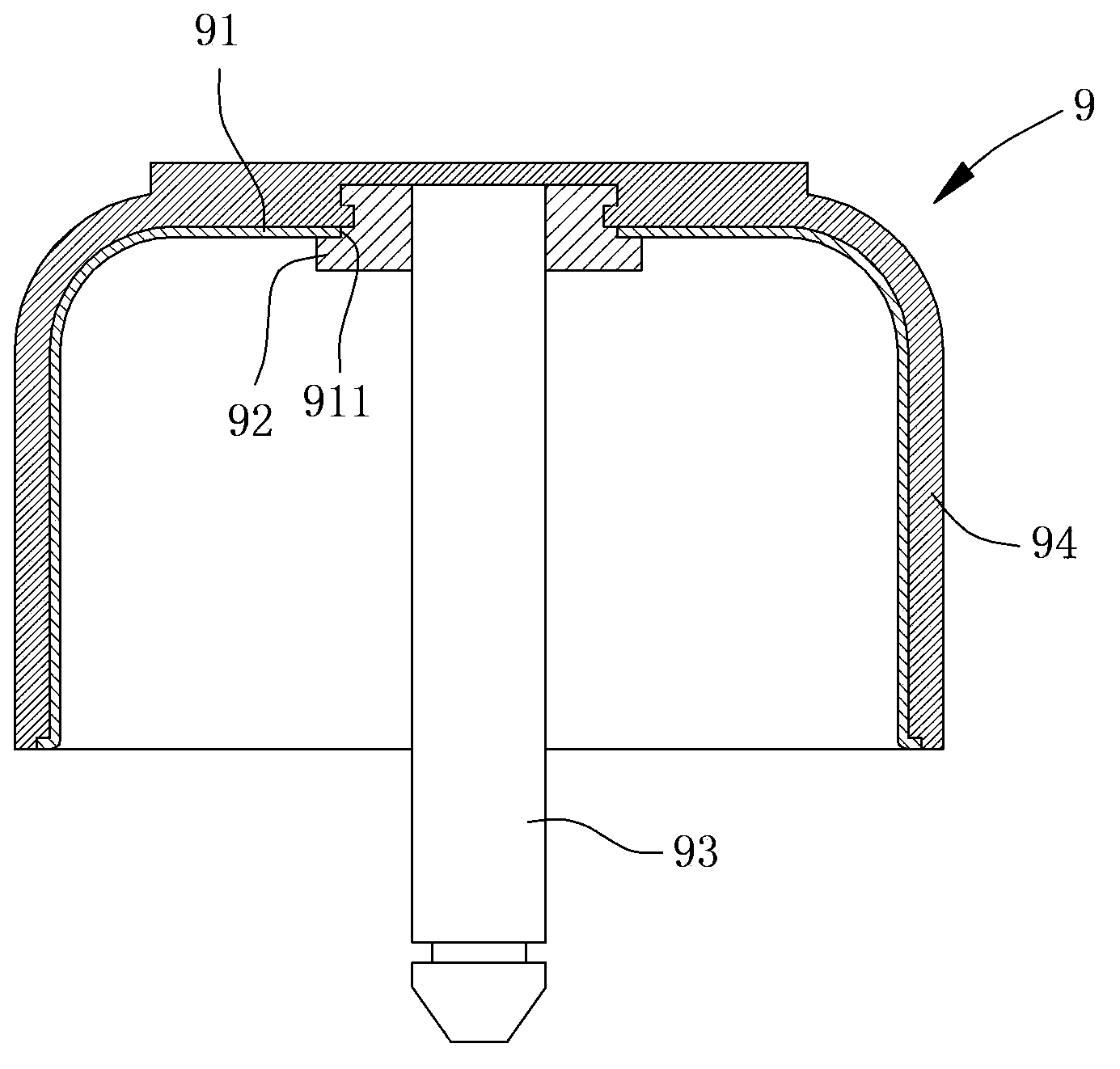
A technology for motor rotors and magnetic parts, applied in the field of motor rotors and their magnetic sealing parts, which can solve the problems of reduced assembly convenience, no structural design of the motor shell 91, and increased manufacturing costs of the motor rotor 9

Active Publication Date: 2014-03-26
SUNON ELECTRONICS (BEIHAI) CO LTD
View PDF8 Cites 4 Cited by
  • Summary
  • Abstract
  • Description
  • Claims
  • Application Information

AI Technical Summary

Problems solved by technology

[0006] However, the rotating shaft 93 of the aforementioned existing motor rotor 9 must still be combined with the motor housing 91 by means of the joint 92, and the hub 94 is used to integrally cover the motor housing 91 and the joint 92; in other words, the existing motor rotor The motor housing 91 of 9 does n

Method used


Image

  • Motor rotor and magnet sealing piece thereof
  • Motor rotor and magnet sealing piece thereof
  • Motor rotor and magnet sealing piece thereof

Examples


Embodiment Construction

[0045] In order to make the above-mentioned and other objects, features and advantages of the present invention more comprehensible, the preferred embodiments of the present invention are specifically cited below, together with the accompanying drawings, as follows:

[0046] Please refer to image 3 As shown, the motor rotor of the present invention includes a magnetic enclosure 1 , a rotating shaft 2 and a hub 3 . Wherein the magnetic sealing member 1 is used to combine with the rotating shaft 2 , and the hub 3 is integrally combined with the rotating shaft 2 and the hub 3 by injection molding.

[0047] The magnetic sealing part 1 can be made into various geometric shapes with the help of thin metal plates, such as stamping, to provide magnetic sealing effects; please refer to Figure 4 As shown, the magnetic sealing member 1 has an opposite first surface 11 and a second surface 12, and is provided with an assembly hole 13 and several positioning holes 14 passing through the...


PUM


Abstract

The utility model provides a motor rotor which comprises a magnet sealing piece, a rotating shaft and a hub, wherein the magnet sealing piece is provided with a first surface and a second surface opposite to each other, and an assembly hole penetrating through the first surface and the second surface; a fixedly connecting part is arranged at the periphery of the assembly hole and axially extends from the second surface to the first surface; a joint end is arranged on the rotating shaft, the joint end is combined with the assembly hole of the magnet sealing piece, and the fixedly connecting part of the magnet sealing piece is combined with the peripheral surface of the rotating shaft near the joint end; the hub is integrally combined with the magnet sealing piece and the rotating shaft; therefore, the bonded area of the magnet sealing piece and the rotating shaft can be increased effectively through the fixedly connecting part.

Description

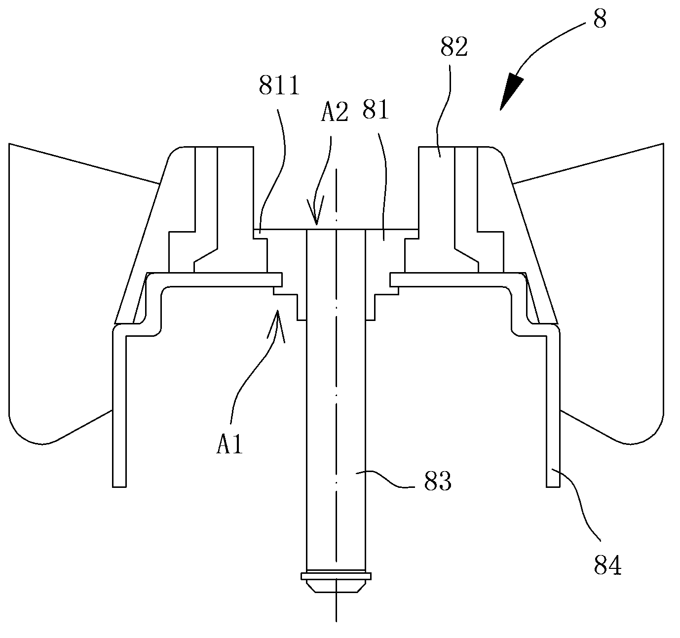
technical field [0001] The invention relates to a motor rotor and its magnetic sealing part, in particular to a motor rotor capable of increasing the combination stability of the magnetic sealing part and the rotating shaft. Background technique [0002] Please refer to figure 1 As shown, it is the Taiwan Utility Model No. I279063 "Fan and its Rotor" patent case, which discloses a more common existing motor rotor 8, which includes a joint 81, an impeller 82 and a Shaft 83. The joint 81 has a flange portion 811; the impeller 82 is integrally formed on the outer periphery of the joint 81 by injection molding, and the impeller 82 is fitted with the flange 811 of the joint 81; the rotating shaft 83 One end is connected to the joint part 81 , and is riveted to a motor housing 84 by means of the joint part 81 . Accordingly, the motor rotor 8 can be applied to a motor structure, and when the stator of the motor structure drives the rotating shaft 83 to rotate, the impeller 82 ca...

Claims


Application Information

Patent Timeline
IPC IPC(8): H02K1/27H02K1/28
Inventor 吕有原
Owner SUNON ELECTRONICS (BEIHAI) CO LTD
Why Eureka
Try Eureka