Dustproof mining camera

A camera and dust-proof technology, which is applied in the field of cameras, can solve the problems of dust-proof failure, easy residual watermark on the lens, and contamination of the camera lens, so as to achieve the effect of maintaining cleanliness

Inactive Publication Date: 2014-03-26
HUAINAN MINING IND GRP
View PDF5 Cites 14 Cited by
  • Summary
  • Abstract
  • Description
  • Claims
  • Application Information

AI Technical Summary

Problems solved by technology

Due to the dust in the working environment of mining machinery, the camera lens used for monitoring is easily polluted by dust, which will affect the monitoring image effect
[0003] In order to solve the above-mentioned problem that the camera lens is polluted, the following two methods are mainly used in the prior art: one is to install a nozzle in front of the lens, and to clean the lens by automatically spraying water regularly by the system to keep the lens clean, but this method Additional cleaning water is required, and watermarks are likely to remain on the lens, and the cleaning effect is not good; in order to solve the problem of washing the lens with water, another method is to set a ring-shaped dustproof cover on the camera, and a ring-shaped dust-proof cover is set on it. The air hole and the air outlet hole, the air enters the annular dust cover from the air inlet hole and is ejected from the air outlet hole. The ejected airflow prevents the dust from approaching the camera lens, forming a dust-proof area in front of the lens, which keeps the lens clean However, the connection between the annular dustproof cover and the camera in this kind of gas dustproof device is unstable and reliable, and it is prone to fall off and damage, resulting in dustproof failure

Method used


Image

  • Dustproof mining camera
  • Dustproof mining camera

Examples


Embodiment Construction

[0015] The present invention will be further described in detail below in conjunction with the accompanying drawings and specific embodiments.

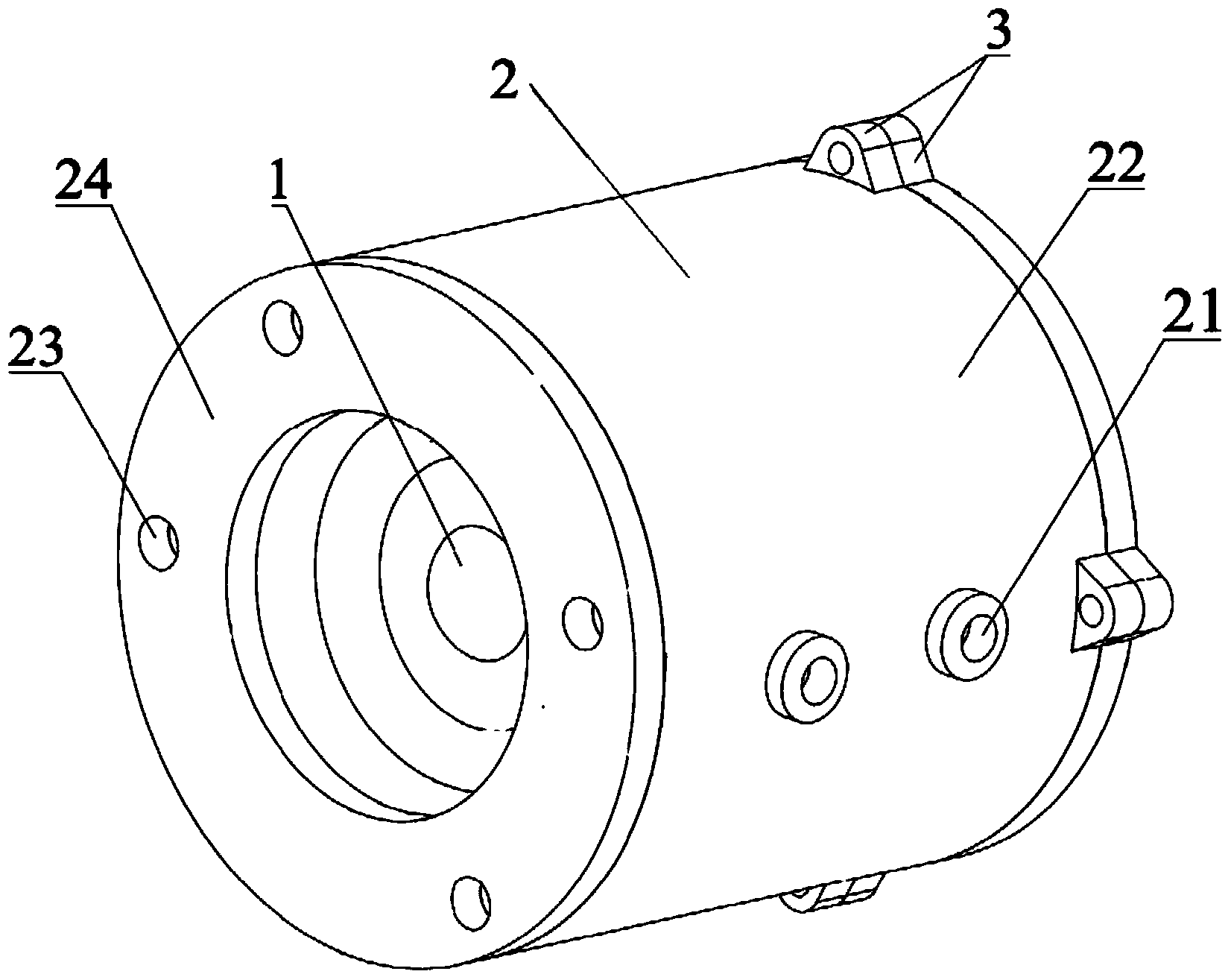
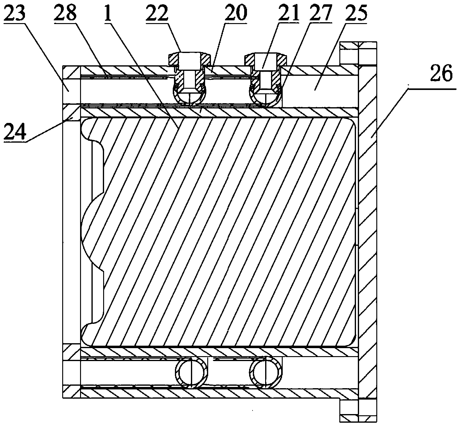
[0016] Such as figure 1 As shown in and 5, a mining dust-proof camera head of the present invention includes an inner layer sleeve 20 for being sleeved on the outside of the camera head, an outer layer sleeve 22 is sleeved outside the inner layer sleeve 20, and the inner sleeve A gas chamber 25 is formed between the layer sleeve 20 and the outer sleeve 22; the front end cover 24 is arranged at the front end of the gas chamber 25, and the rear end cover 26 is arranged at the end of the gas chamber 25; The front end cover 24 is provided with an air outlet 23, and the wall of the outer sleeve 22 is provided with an air inlet 21; the gas cavity 25 is provided with an arc pipe 27 and a connecting pipe 28; The arc tube 27 is provided with a hole communicating with the air inlet 21; the front end of the communicating tube 28 is connected wi...


PUM


Abstract

The invention discloses a dustproof mining camera. The dustproof mining camera comprises an inner layer sleeve arranged outside a camera body in a sleeved mode, an outer layer sleeve is arranged outside the inner layer sleeve in a sleeved mode, and a gas cavity is formed between the inner layer sleeve and the outer layer sleeve. A front end cover covers the front end of the gas cavity, and a rear end cover covers the tail end of the gas cavity. A gas outlet hole is formed in the front end cover, and a gas inlet hole is formed in the wall of the outer layer sleeve. According to the dustproof mining camera, gas for cleaning enters a cavity defined by the inner layer sleeve, the outer layer sleeve, the front end cover and the rear end cover in an enclosing mode through the gas inlet hole and is blown out through the gas outlet hole, the blown out gas flow generates a gas field in front of a lens to form a dust separation area, thus, dust in the environment can be prevented from falling onto the lens, the lens is kept clean, and it can be guaranteed that pictures can be shot normally and clearly by the camera.

Description

technical field [0001] The invention relates to a camera, in particular to a mine dustproof camera. Background technique [0002] With the application and popularization of roadway intelligent technology, the technology of installing cameras in mines and underground working equipment and other mining machinery to carry out remote visual monitoring of roadway operations has also developed rapidly. Due to the dust in the working environment of mining machinery, the camera lens used for monitoring is easily polluted by dust, which will affect the monitoring image effect. [0003] In order to solve the above-mentioned problem that the camera lens is polluted, the following two methods are mainly used in the prior art: one is to install a nozzle in front of the lens, and to clean the lens by automatically spraying water regularly by the system to keep the lens clean, but this method Additional cleaning water is required, and watermarks are likely to remain on the lens, and the c...

Claims


Application Information

Patent Timeline
IPC IPC(8): G03B17/02H04N5/225
Inventor 柏云飞
Owner HUAINAN MINING IND GRP
Why Eureka
Try Eureka