
Torsional vibration damper or rotationally elastic coupling

A technology for torsional vibration dampers and elastic couplings, applied in the direction of elastic couplings, shock absorber-spring combinations, couplings, etc., can solve the problem of reducing overflow grooves between cavities, affecting damping characteristics, reducing Problems such as complex assembly of vibrators or couplings, etc., achieve the effect of reducing costs and simplifying assembly

Active Publication Date: 2014-03-26
ELLERGON ANTRIEBSTECHN
View PDF8 Cites 5 Cited by
  • Summary
  • Abstract
  • Description
  • Claims
  • Application Information

AI Technical Summary

Problems solved by technology

[0007] The use of an additional inner ring leads to complex and laborious assembly of the shock absorber or coupling
A slight relative movement of the leaf spring assembly and the middle plate, or a further relative movement, at this time the effect of setting the inner ring may appear, and the proper arrangement of the leaf spring assembly is very difficult
In addition, setting the intermediate piece may reduce the overflow groove between the cavities, thereby affecting the damping characteristics

Method used


Image

  • Torsional vibration damper or rotationally elastic coupling
  • Torsional vibration damper or rotationally elastic coupling
  • Torsional vibration damper or rotationally elastic coupling

Examples


Embodiment Construction

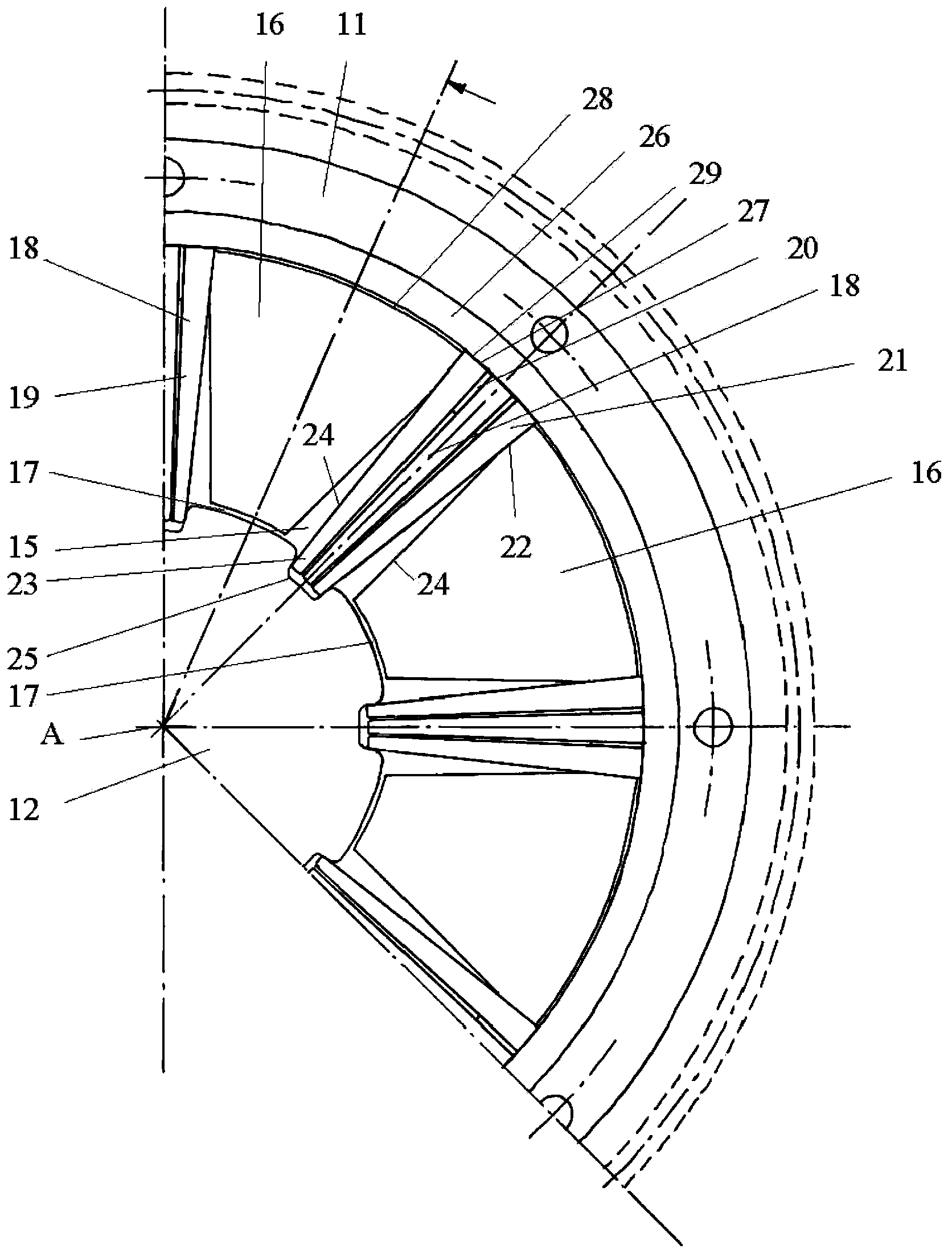
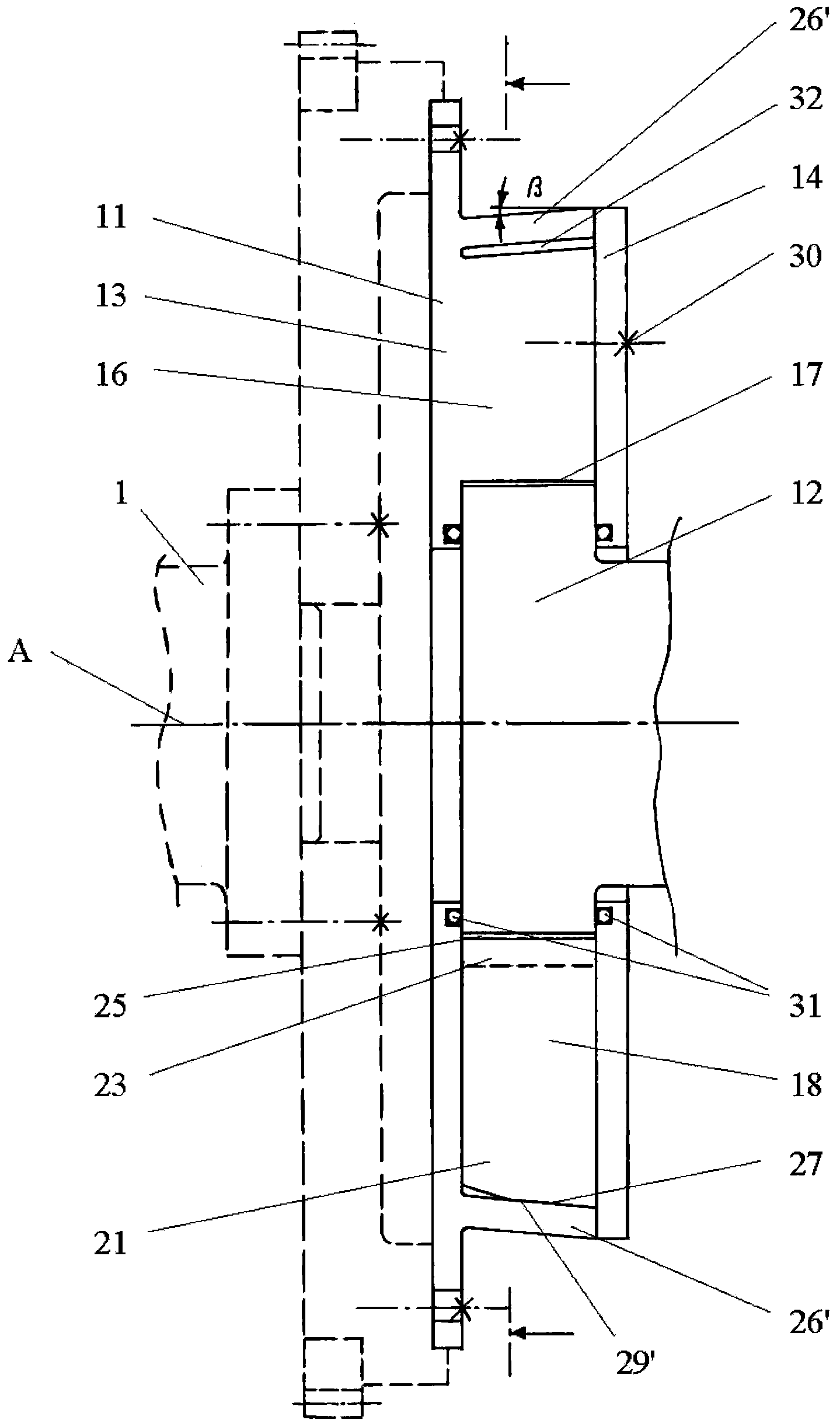
[0031] Such as figure 1 , 2 As shown, the rotating elastic coupling 10 is used to connect the first shaft 1 and the second shaft 2 and transmit torque between the first shaft 1 and the second shaft 2, and reduce vibration or change the torque during torque transmission .

[0032] The coupling 10 comprises a housing 11 , which is rotatable about a longitudinal axis A, and an inner part 12 which is arranged inside the housing 11 and which rotates about the longitudinal axis A relative to the housing 11 . The inner part 12 and the outer shell 11 are coaxial.

[0033] The housing 11 comprises a first flange 13 and a second flange 14 which are arranged facing each other and are sealed from the internal part 12 .

[0034] The shell 11 and the inner part 12 radially delimit a plurality of cavities 15, and the cavities 15 are filled with a damping medium, such as high-pressure oil. The cavities 15 are arranged sequentially along the circumferential direction of the inner part 12 a...


PUM


Abstract

A torsional vibration damper or a rotationally elastic coupling comprises: an outer housing (11) including a flange (13); an inner part (12); a plurality of intermediate pieces (16) arranged around the inner part and forming a plurality of chambers (15) filled with a damping medium; a plurality of leaf spring assemblies (18) being arranged in said chambers and having outer end portions (21) engaging with receptacles (22) formed between neighbouring intermediate pieces (16) and inner end portions (23) engaging with the inner part; and a clamping ring (26) extending around the intermediate pieces (16) and the leaf spring assemblies (18). The receptacles (22) and the corresponding radially outer end portions (21) of the leaf spring assemblies (18) taper radially inwardly. The intermediate pieces (16) are formed integrally on a flange (13). The radially outer end portions (21) of the leaf spring assemblies (18) are urged radially into the receptacles (22) by the clamping ring (26, 26'). This configuration simplifies assembly of the damper or coupling and provides precise positioning of the leaf spring assemblies. Moreover, it is possible to obtain desired damping properties within narrow ranges of tolerance.

Description

technical field [0001] The invention relates to torsional vibration dampers or rotationally elastic couplings. Background technique [0002] Torque is transmitted from the inner part to the housing or vice versa by means of the leaf spring assembly, while at the same time the leaf spring assembly limits relative rotation between the inner part and the housing. Then, the inner part and the housing vibrate relative to each other along the circumferential direction of the shock absorber or coupling. Due to the rotational vibration, the shock-absorbing medium in the cavity moves accordingly to produce a vibration-damping effect. In a coupling, the outer shell is connected to the first shaft and the inner part is connected to the second shaft. In shock absorbers, internal components or housings can be connected to the structure that needs to be damped. [0003] Such shock absorbers and couplings were originally used in the drive trains of large two-stroke or four-stroke diesel...

Claims


Application Information

Patent Timeline
IPC IPC(8): F16D3/56
CPCF16F15/1336F16F15/16F16D3/14F16F15/133F16D13/64F16D3/56F16F15/1215F16D3/12F16F13/00
Inventor 马提亚·盖斯林格科尼利斯·盖斯林格
Owner ELLERGON ANTRIEBSTECHN
Learn More