Energy storage device

A technology of an energy storage device and a casing, applied in the field of machinery, can solve the problems of waste and unreasonable utilization of machinery, and achieve the effect of simple structure and reasonable design

Inactive Publication Date: 2014-03-26
陈永申
View PDF6 Cites 6 Cited by
  • Summary
  • Abstract
  • Description
  • Claims
  • Application Information

AI Technical Summary

Problems solved by technology

In the process of mechanical equipment operation, a lot of mechanical energy is not used rationally and is wasted in vain

Method used


Image

  • Energy storage device
  • Energy storage device

Examples


Embodiment 1

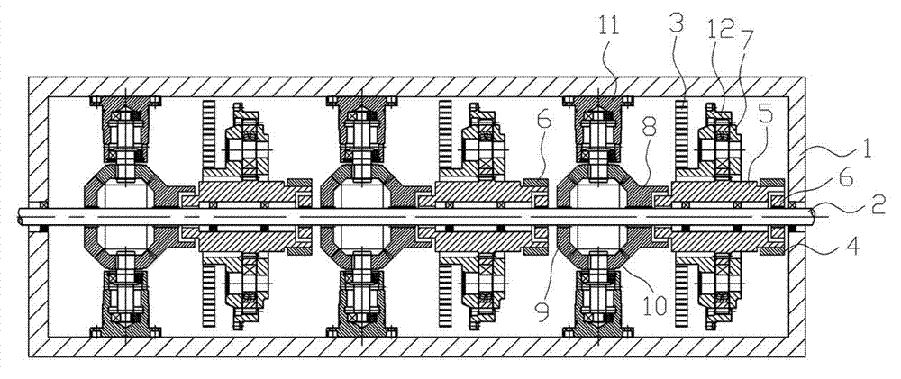
[0009] like figure 1 As shown, it includes a housing 1. A through shaft 2 is arranged inside the housing 1. An energy storage assembly and a reverse gear assembly are set on the through shaft 2. The energy storage assembly consists of an energy storage coil spring 3, a planetary reduction mechanism and a self-locking The electromagnetic clutch 4 is composed of the input end 5 (sun gear) of the planetary reduction mechanism, which is sleeved on the through shaft 2 and connected with the through shaft 2 through the electromagnetic clutch 6. The output end 7 (rotor, the part used to fix the planetary gear) of the planetary reduction mechanism ) is connected with the energy storage coil spring 3, the outer ring gear 12 and the other end of the coil spring are respectively fixed on the housing 1, and the reverse gear assembly consists of an input bevel gear 8 and an output bevel gear 9 respectively set on the through shaft The input bevel gear 8 is connected to the input end 5 of t...

Embodiment 2

[0011] like figure 2 As shown, it is composed of multiple groups of energy storage components and reverse gear components. Multiple sets of energy storage components can store energy separately or simultaneously, and realize stepwise input and output according to load.

[0012] In the energy storage process, take automobile braking as an example. When braking, the sensor can identify the braking action and cut into the electromagnetic clutch 6 between the sun gear 5 and the through shaft 2 to input the braking energy into the energy storage coil spring 3; when the braking is over, Loosen the electromagnetic clutch 6 between the sun gear 5 and the through shaft 2, cut into the self-locking electromagnetic clutch 4 to lock the energy storage coil spring 3; The electromagnetic clutch 6 between the bevel gear 8 and the sun gear 5 realizes the energy release process.

[0013] The invention can be applied in automobile braking, can be installed between the gearbox and the driving...


PUM


Abstract

The invention discloses an energy storage device and relates to the technical field of machinery. A through shaft (2) is arranged in a shell (1) and sleeved with an energy storage assembly and a reverse gear assembly. The energy storage assembly is composed of an energy storage coil spring (3), a planet reducing mechanism and a self-locking electromagnetic clutch (4). The input end (5) of the planet reducing mechanism is arranged on the through shaft (2) in a sleeved mode and connected with the through shaft (2) through an electromagnetic clutch (6). The output end (7) of the planet reducing mechanism is connected with the energy storage coil spring (3). The reverse gear assembly is composed of an input bevel gear (8) and an output bevel gear (9), wherein the through shaft (2) are sleeved with the input bevel gear (8) and the output bevel gear (9) respectively, the input bevel gear (8) is connected with the input end (5) of the energy storage assembly through the electromagnetic clutch (6), and the output bevel gear (9) is connected with the through shaft (2) through the electromagnetic clutch (6), or is directly fixed to the through shaft (2). The energy storage device has the advantages of being simple in structure and reasonable in design, and mechanical energy can be converted to elastic potential energy to be utilized reasonably.

Description

technical field [0001] The invention relates to the field of mechanical technology, in particular to an energy storage device using coil springs. Background technique [0002] With the increasing tension of global energy sources, the development of energy-saving products is becoming more and more urgent. During the operation of mechanical equipment, a lot of mechanical energy is not used rationally and is wasted in vain. For example, during the braking process of a car, in order to stop the car, the friction of the brake pads will be used to do work, which will convert kinetic energy into heat energy and consume it. If this part of kinetic energy can be reasonably stored and utilized, good energy-saving effect and economic value will be achieved. Contents of the invention [0003] The technical problem to be solved by the present invention is to provide an energy storage device that can convert mechanical energy into elastic potential energy for rational use. [0004] ...

Claims


Application Information

Patent Timeline
Patent Type & Authority Applications(China)
IPC IPC(8): F03G1/00F16H33/02
Inventor 陈永申
Owner 陈永申
Why Eureka
Try Eureka