
Manufacturing method of steel skeleton structure

A manufacturing method and technology for structures, which can be applied in building structures, buildings, etc., can solve problems such as difficulty in obtaining sufficient load bearing capacity, easy bending of partitions, and many longitudinal gaps.

Inactive Publication Date: 2016-12-21
ARCREATE
View PDF5 Cites 0 Cited by
  • Summary
  • Abstract
  • Description
  • Claims
  • Application Information

AI Technical Summary

Problems solved by technology

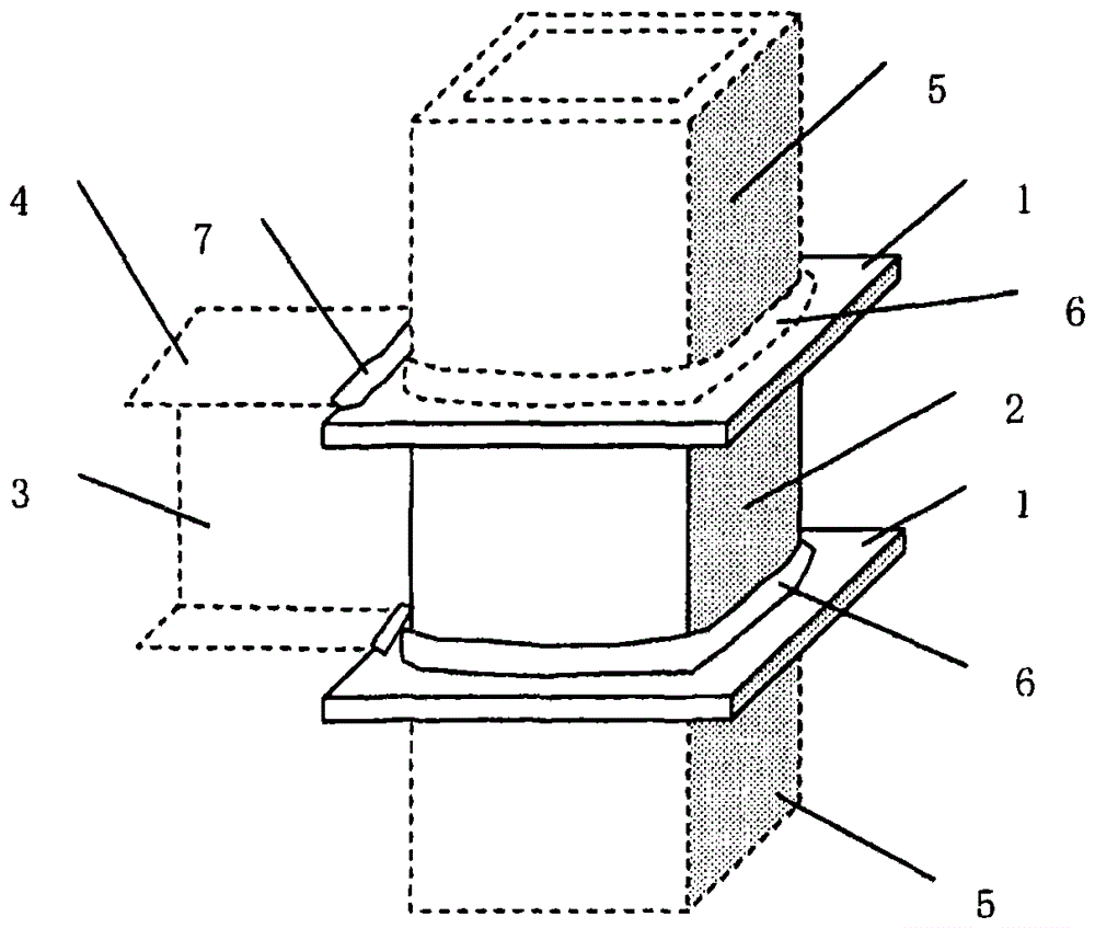
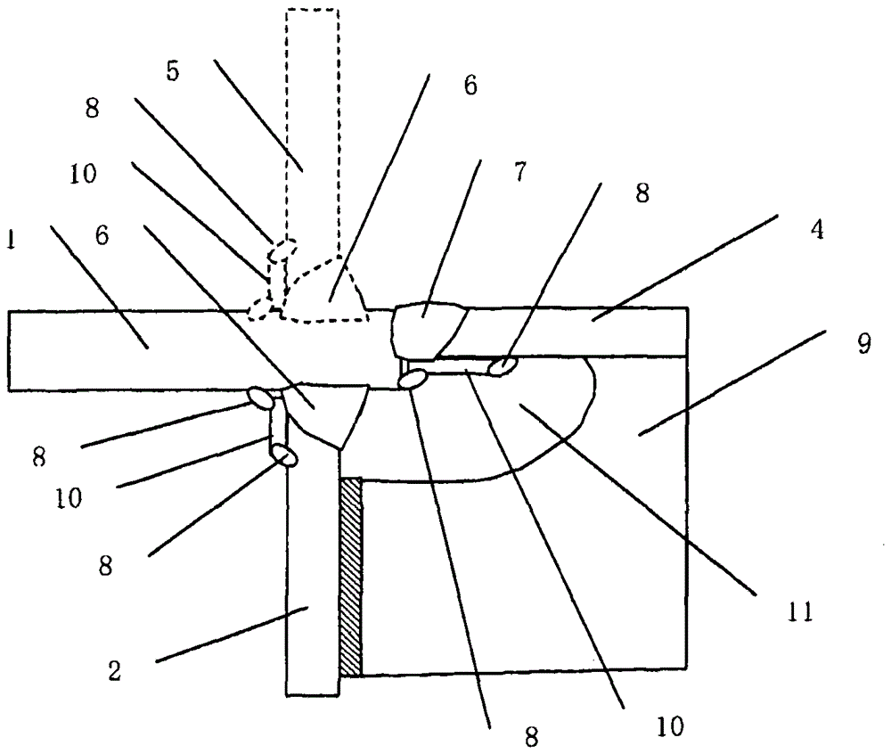
Therefore, there are the following problems: the cost of parts manufacturing is high, and the partition plate protruding from the square steel pipe column after the dice body is manufactured is easy to bend, so the so-called umbrella bending phenomenon occurs, and the gap between the partition plate 1 and the beam flange 4 is easy to be bent. misread
[0025] (1) In a simple longitudinal gap, the welding at the end of the gap has edges and corners, and defects are prone to occur during welding
[0026] (2) The number of longitudinal slits is large, and many small screw holes are required, so the cost of opening holes is spent
[0027] (3) Metal fittings with complex shapes are split type, and 8 pieces are required for 1 column-beam junction
[0029] (5) The main body of the metal part is a slanted material at 45° relative to the beam axis direction, and it is difficult to obtain sufficient bearing capacity for the load in the beam axis direction
[0030] (6) There are metal parts, small screws, many openings, etc., the number of parts is large, the shape is complicated, it is difficult to assemble, and the cost is higher than that of the partition method
In this method, although the welding of the square steel pipe column and the inner partition is partial, the cross-sectional area of ​​the groove becomes the object to be welded, and the wall thickness (plate thickness) of the column and the wall thickness (plate thickness) of the beam flange become larger as they increase. There is a problem that the amount of welding increases dramatically, and there is a problem that welding efficiency decreases

Method used


Image

  • Manufacturing method of steel skeleton structure
  • Manufacturing method of steel skeleton structure
  • Manufacturing method of steel skeleton structure

Examples


Embodiment 1

[0080] In the invention described in technical scheme 1, in Figure 11 to Figure 14 represents the state of implementation of the present invention. Figure 11 It is an explanatory diagram of the preparation status of the 4-sided box-shaped steel plate before assembling the 4-sided box-shaped steel pipe column, and the through-hole is opened in the column steel plate in advance. Figure 12 It shows the initial assembly state of installing the separator into the two sides of the steel plate for 4-sided box-shaped steel pipe. role of positioning. Figure 13 It is an intermediate assembly state in which the separator is incorporated into the 3 sides of the steel plate for the 4-sided box-shaped steel pipe, Figure 14 Indicates the state of intermediate assembly where separators are installed on the four sides of the steel plate for box-shaped steel pipes on four sides, and then, if the corners of the steel pipes with bevels are welded in the direction of the column axis, in add...

Embodiment 2

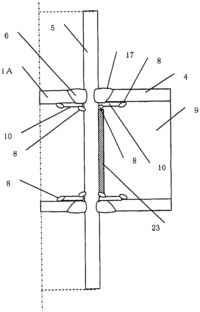
[0084] In the invention described in claim 1, for the purpose of welding stably from the outside of the column, it can be as follows Figure 10 As shown in an example of (A), a backing plate 10 is provided inside the through hole. In addition, if the backing plate 10 is attached in advance, it can also serve as a guide portion or a stopper for installing the partition plate 1A in the through hole.

Embodiment 3

[0086] Although the present invention has been described with respect to square steel pipes, it is also suitable for circular steel pipes. For example, if the circumference of a circular steel pipe is divided into a square steel pipe, it can be applied similarly to the square steel pipe. In this case, the circumferential welding of the circular steel pipe is divided into two at least in the axial direction of the welded joint, the plan view of the inner partition is circular, and the plan view of the end of the beam is an arc.


PUM


Abstract

The invention provides a steel-framed structure manufacturing method. In the past, at a building steel-framed column and girder joint part, square steel pipe columns are cut off according to building layers and assembled in the mode that the square steel pipe columns penetrate through partition plates, the method is complicated, more work hours for manufacturing is consumed, degradation and deformation of the peripheries of the partition plates are caused, even if the columns are not cut off according to the layers, electro-slag welding has to be performed between four-side box columns and the partition plates so that a large welding amount is generated, and if welding is performed on the partition plates and the columns at the ultra-high input heat energy of 500-1000KJ / cm, cracking or degradation such as lamellar tearing of the columns is prone to occurring. In the steel-framed structure manufacturing method, for four-side box-shaped steel pipe columns with the thickness being above 25mm and the diameter being above 400mm, the steel pipe columns are not cut off according to layers, welding is performed on a part of through holes formed in the box-shaped steel pipe columns and the ends of inner partition plates of a protrusion with outward grooves in the whole periphery of the protrusion in a small welding amount and low input heat energy mode, H-shaped steel girders are connected through a multilayer stacked welding portion comprising through hole welding portions in a welding mode, and therefore the problems are solved.

Description

technical field [0001] The present invention relates to providing a protrusion on a part of the peripheral end of an inner partition in a thick-walled, large-diameter column-beam junction of a building steel frame structure, providing a bevel on the entire circumference of the protrusion, and having The protruding inner partition plate with the bevel and the beam are directly connected by welding through the column through-hole. Background technique [0002] In the prior art, in the column-beam joint of the building steel frame structure, the joint such as figure 1 As shown, a dice body is formed by welding 6 between a partition plate 1 formed of a thin steel plate and a shorter square steel pipe 2, and the dice body is welded to the H-shaped steel beam flange 4 7, and then the dice body is connected to the H-shaped steel beam flange 4. The square steel pipe columns 5 are often formed by welding and joining. In this prior art, such as figure 2 As shown, the welding 6 of ...

Claims


Application Information

Patent Timeline
Patent Type & Authority Patents(China)
IPC IPC(8): E04B1/58
Inventor 内田昌克岩乡俊二岩乡速雄
Owner ARCREATE
Learn More