Oil-electric hybrid electric vehicle multi-mode drive system
A hybrid electric vehicle and drive system technology, which is applied to the arrangement of multiple different prime movers, power units, vehicle components, etc.
- Summary
- Abstract
- Description
- Claims
- Application Information
AI Technical Summary
Problems solved by technology
Method used
Image
Examples
Embodiment 1
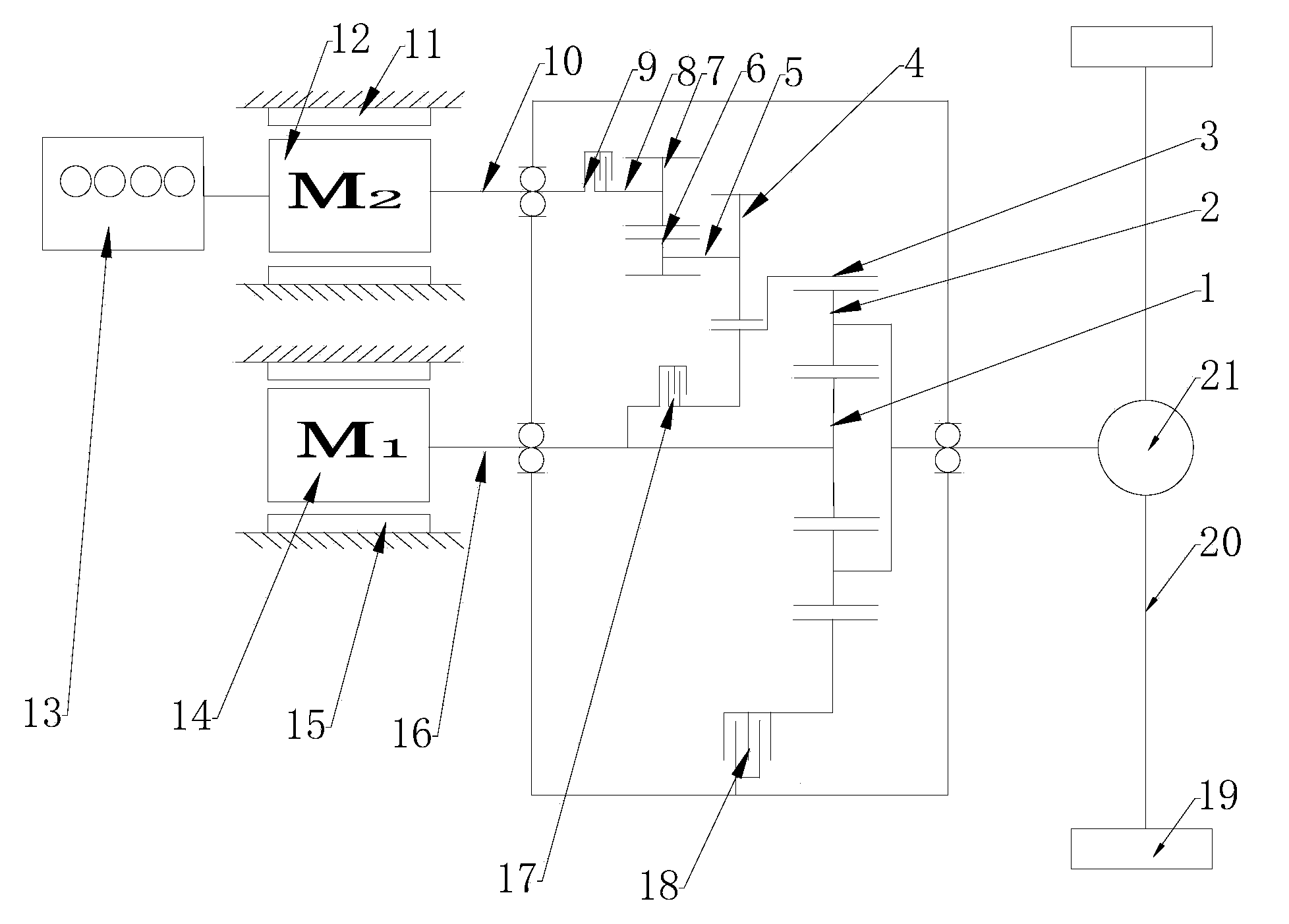
[0033] like figure 2 As shown, a multi-mode drive system for a hybrid electric vehicle includes an engine 13, a first motor 14, a second motor 12, a planetary mechanism, a first clutch 9, a second clutch 17, a brake 18, a motor controller, and an ECU , drive axle 21, axle shaft 20 and wheels 19; the first clutch 9 and the second clutch 17 both adopt hydraulic multi-disc clutches, and the brake 18 adopts hydraulic multi-disc brakes; the planetary mechanism includes sun gear 1, planetary carrier 2 and gear circle 3; the second motor 12 is installed on the second motor base 11, one end is connected with the engine 13, and the other end is connected with the second motor rotor shaft 10; one end of the first clutch 9 is connected with the second motor rotor shaft 10, and the other end The connecting shaft 8 is connected with the first gear 7, and the first gear 7 meshes with the second gear 6 to form a gear pair; the second gear 6 is connected with the intermediate shaft 5, and th...
Embodiment 2
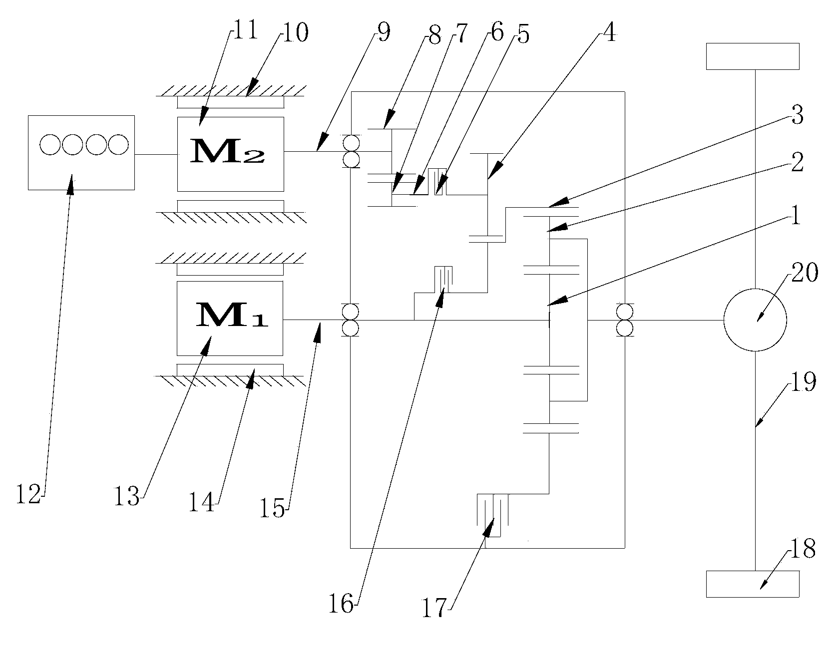
[0044] As shown in Figure 3, a multi-mode drive system for a hybrid electric vehicle includes an engine 12, a first motor 13, a second motor 11, a planetary mechanism, a first clutch 5, a second clutch 16, a brake 17, a motor control device, ECU, drive axle 20, axle shaft 19 and wheels 18; the first clutch 5 and the second clutch 16 both adopt hydraulic friction plate clutches; the brake 17 adopts hydraulic friction plate brakes; the planetary mechanism includes sun gear 1, planet carrier 2 and the ring gear 3; the second motor 11 is installed on the second second motor base 10, one end is connected with the engine 12, and the other end is connected with the second motor rotor shaft 9; one end of the first clutch 5 is connected with the connecting shaft 6, The other end is externally meshed with the ring gear 3 through the third gear 4; the connecting shaft 6 is also connected with the first gear 7, and the first gear 7 meshes with the second gear 8 to form a gear pair; the sec...
Embodiment 3
[0047] The second clutch of this embodiment adopts a diaphragm spring clutch, which is mainly composed of a clutch housing, a diaphragm spring, a pressure plate, a friction plate and a release bearing; the first clutch adopts a hydraulic multi-plate clutch, and the brake adopts a caliper disc type. The difference from Embodiment 1 is that the rotor shaft of the second motor is connected to the transmission mechanism, and the transmission mechanism is connected to the ring gear through internal meshing. The working principle is the same as that of Embodiment 1.
PUM
 Abstract
Description
Claims
Application Information
 - R&D
- Intellectual Property
- Life Sciences
- Materials
- Tech Scout
- Unparalleled Data Quality
- Higher Quality Content
- 60% Fewer Hallucinations
Browse by: Latest US Patents, China's latest patents, Technical Efficacy Thesaurus, Application Domain, Technology Topic, Popular Technical Reports.
© 2025 PatSnap. All rights reserved.Legal|Privacy policy|Modern Slavery Act Transparency Statement|Sitemap|About US| Contact US: help@patsnap.com


