Tool manufacturing method special for radiant tube machining

A manufacturing method and technology of radiant tubes, applied to metal processing equipment, metal processing machine parts, positioning devices, etc., can solve the problems of low efficiency and cumbersome processing steps, and achieve the advantages of convenient use, high processing precision, and adaptability to mass production Effect

Inactive Publication Date: 2014-03-26
QINGDAO NPA IND
View PDF0 Cites 4 Cited by
  • Summary
  • Abstract
  • Description
  • Claims
  • Application Information

AI Technical Summary

Problems solved by technology

[0006] In order to overcome the above-mentioned problems existing in the prior art field, the object of the present invention is to provide a method for manufacturing special tooling for radiant tube processing, which solves the problem of cumbersome and low-efficiency processing steps for processing the transverse holes on the radiant tube wall

Method used


Image

  • Tool manufacturing method special for radiant tube machining
  • Tool manufacturing method special for radiant tube machining

Examples


Embodiment

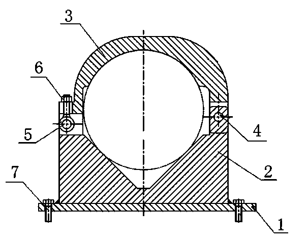
[0021] refer to Figure 1-Figure 2 , the manufacturing method of special tooling for radiant tube processing of the present embodiment, its manufacturing steps are as follows:

[0022] Make the positioning mechanism according to the drawings: fix the V-shaped base 2 on the bottom plate 1; set the rotating pressure plate 3 on the V-shaped base 2 and cooperate with it, and one side of the rotating pressure plate 3 is connected with the V-shaped base 2 through the rotating pin 4, The other side is connected with the V-shaped base 2 through mutually matched bolts 5 and nuts 6 .

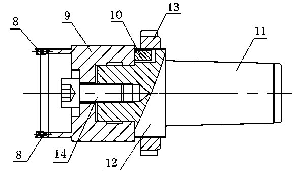
[0023] Make cutter mechanism according to drawing: make knife cover 9, the beginning of knife cover 9 is provided with the weld groove that symmetry cooperates with cutter head 8, and cutter cover 9 end both sides are respectively fixed with cutter cover anti-rotation plate 10; Be fixedly arranged on the welding groove of knife cover 9; Make cutter connector, connector one end is cone 11, and the other e...


PUM


Abstract

The invention discloses a tool manufacturing method special for radiant tube machining. The manufacturing method includes the step of manufacturing a positioning mechanism and the step of manufacturing a cutting knife mechanism. In the step of manufacturing the positioning mechanism, a V-shaped base is fixed to a bottom plate through a fastening bolt, a rotating pressing plate is arranged on the V-shaped base, one side of the rotating pressing plate is connected with the V-shaped base through a rotating pin, and the other side of the rotating pressing plate is connected with the V-shaped base through a bolt and a nut. In the step of manufacturing the cutting knife mechanism, a knife sleeve is manufactured, welding grooves which are symmetrical and matched with tool bits are formed in the start end of the knife sleeve, knife sleeve rotation prevention plates are fixedly arranged on the two side faces of the tail end of the knife sleeve respectively, the tool bits are fixedly arranged on the welding grooves of the knife sleeve, a cutting knife connecting piece is manufactured, one end of the connecting piece is a cone, the other end of the connecting piece is a cylinder, the large end of the cone is connected with one end of the cylinder, the other end of the cylinder is connected with the tail end of the knife sleeve through a fastening screw, and the cylinder is sleeved with a thread bushing and matched with the thread bushing in a threaded mode. A tool manufactured through the method is simple in structure, convenient to use, high in accuracy and capable of meeting the requirement for mass production, and the efficiency can be improved by more than 5 times.

Description

[0001] technical field [0002] The invention belongs to a manufacturing method of a hole processing device, and in particular relates to a manufacturing method of a special frock for radiant tube processing. [0003] Background technique [0004] The transverse holes on the wall of the metallurgical radiant tube are hard and sticky, and the hole size is large, making it difficult to process. When processing holes on a small horizontal boring machine, it needs to be drilled in one step and reamed in 3 to 4 steps before it can be completed. However, multiple tool changes and repeated cutting are required during the processing, and the processing time is as long as 50 minutes, resulting in low production efficiency. And the strength of the boring head of the horizontal boring machine is insufficient, and the effect is not good enough when used on the horizontal boring machine. [0005] Contents of the invention [0006] In order to overcome the above-mentioned problems e...

Claims


Application Information

Patent Timeline
Patent Type & Authority Applications(China)
IPC IPC(8): B23Q3/06B23D79/00
CPCB23B51/0473B23Q3/064B23B51/04
Inventor 古朝雄
Owner QINGDAO NPA IND
Why Eureka
Try Eureka