Powerful vacuum chuck

A vacuum suction cup, powerful technology, applied in the direction of suction cups, turning equipment, connecting components, etc., can solve the problems of not meeting the requirements of the workpiece, and achieve the effect of high degree of automation, simple structure, and enhanced suction

Inactive Publication Date: 2014-03-26
TIANJIN HUARONG PNEUMATIC & HYDRAULIC COMPLETE SYST
View PDF0 Cites 0 Cited by
  • Summary
  • Abstract
  • Description
  • Claims
  • Application Information

AI Technical Summary

Problems solved by technology

[0004] The adsorption force of traditional vacuum chucks often cannot meet the requirements of some workpieces

Method used


Image

  • Powerful vacuum chuck

Examples


Embodiment Construction

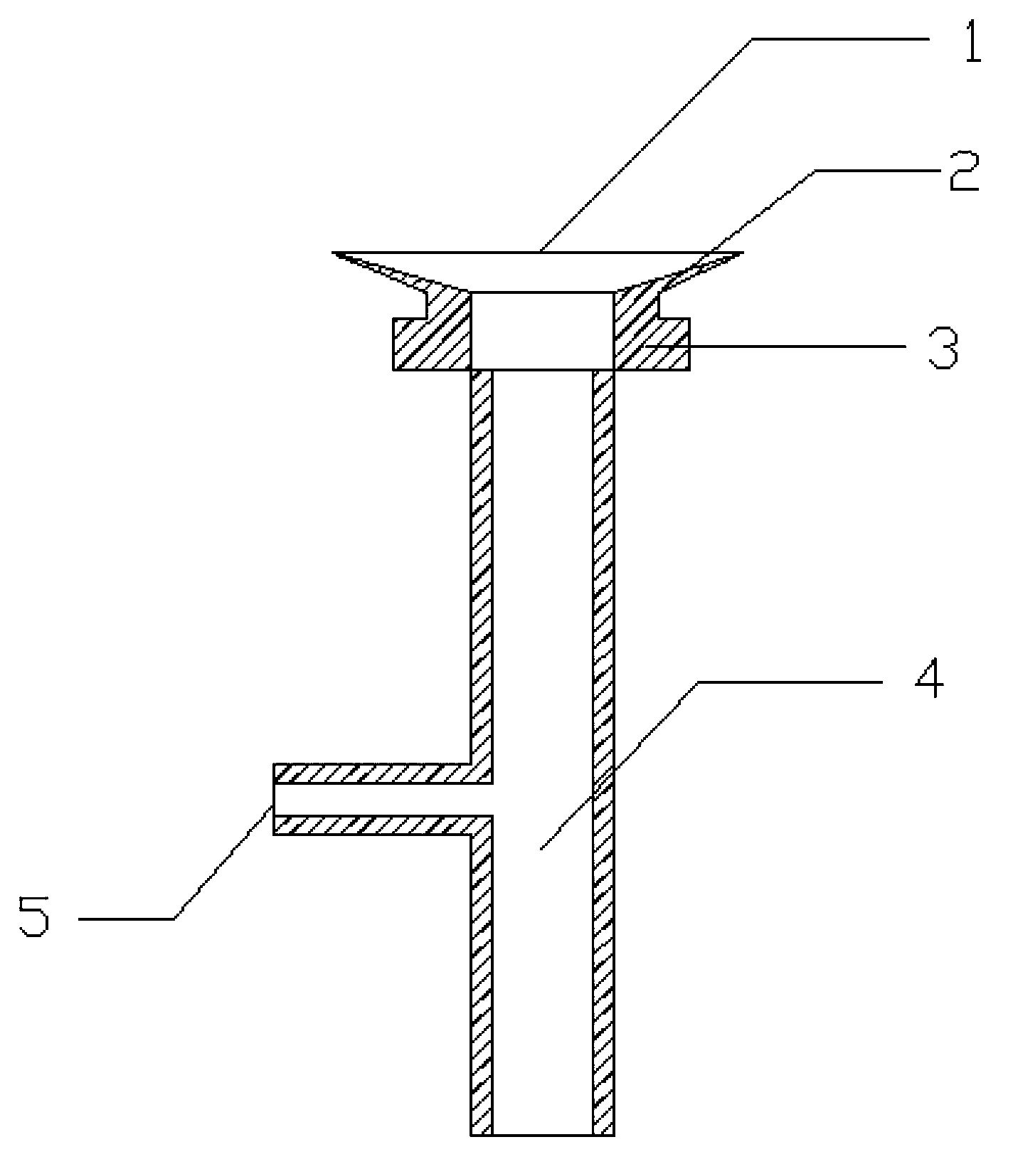
[0012] Such as figure 1 Shown, the present invention is a kind of powerful vacuum suction cup, and the sucker of this powerful vacuum suction cup is the annular circle body of rubber material, and the wall of annular circle body upper half 2 is thinner than the wall of lower half 3, and upper half 2 The inner diameter of the upper half is larger than the inner diameter of the lower half 3, and the inner diameter of the upper half 2 gradually increases from bottom to top.

[0013] In practical application, the inner diameter of the upper half 2 of the annular ring body is larger, which is more conducive to uniform suction around the suction cup. The wall of the lower half 3 of the annular ring body is thicker and not easily deformed, which is convenient for firmly adsorbing the vacuum suction cup 1 on the suction cup seat. The quick connector 5 is connected with the vacuuming device, and when vacuuming, the suction force of the suction cup is stronger.

[0014] The working pr...


PUM


Abstract

The invention provides a powerful vacuum chuck. The powerful vacuum chuck comprises a chuck body and a connecting block. The chuck body is an annular ring body made of rubber, and the annular ring body comprises an upper half portion and a lower half portion, wherein the upper half portion is in the shape of a cone frustum, the wall of the upper half portion is thinner than that of the lower half portion and becomes thinner gradually from bottom to top, and the inner diameter of the upper half portion is larger than that of the lower half portion and becomes larger gradually from bottom to top. The connecting block is located at the bottom of the chuck body and is communicated with the chuck body, an opening is formed in the bottom end of the connecting block, and a fast connector communicated with the connecting block is arranged on the lateral side of the connecting block. The power vacuum chuck has the advantages that the vacuum chuck of the special structure can generate uniform absorbing force; furthermore, because the vacuum chuck is connected with a vacuumizing device, absorbing force is increased, and requirements for absorbing of all kinds of workpieces can be met; the powerful vacuum chuck is high in automation degree and simple in structure and can be widely and conveniently applied to a precision lathe.

Description

technical field [0001] The invention relates to a suction cup, in particular to a powerful vacuum suction cup. Background technique [0002] In the existing technology, the vacuum suction cup is referred to as the suction cup, also known as the vacuum spreader. Generally speaking, it is a kind of sealing lip, which forms a temporary sealed space after the sucked object contacts. The air in the sealed space is a pneumatic element that works by generating a pressure difference between the inside and outside. Its name also has rubber suction nozzle, rubber suction head and so on. [0003] The materials used to produce vacuum suction cups are generally various rubbers, plastics and metals. The vacuum suction cups we often see are made of various rubbers such as NR, NBR, and SE. Using vacuum suction cups to grab products is the cheapest way. [0004] The adsorption force of traditional vacuum chucks often cannot meet the requirements of some workpieces. Contents of the inve...

Claims


Application Information

Patent Timeline
Patent Type & Authority Applications(China)
IPC IPC(8): B23B25/00F16B47/00
CPCB23B25/00F16B47/00
Inventor 徐华生
Owner TIANJIN HUARONG PNEUMATIC & HYDRAULIC COMPLETE SYST
Why Eureka
Try Eureka