
Sliding stamping device

A stamping device and slider technology, applied in the field of machine tool components, can solve the problems of low assembly efficiency and manual feeding, and achieve high assembly efficiency

Inactive Publication Date: 2014-03-26
CHONGQING ZHIRUIDE TECH
View PDF0 Cites 0 Cited by
  • Summary
  • Abstract
  • Description
  • Claims
  • Application Information

AI Technical Summary

Problems solved by technology

[0003] The technical problem to be solved by the present invention is the shortcomings of manual feeding and low assembly efficiency in the prior art,

Method used


Image

  • Sliding stamping device

Examples


Embodiment Construction

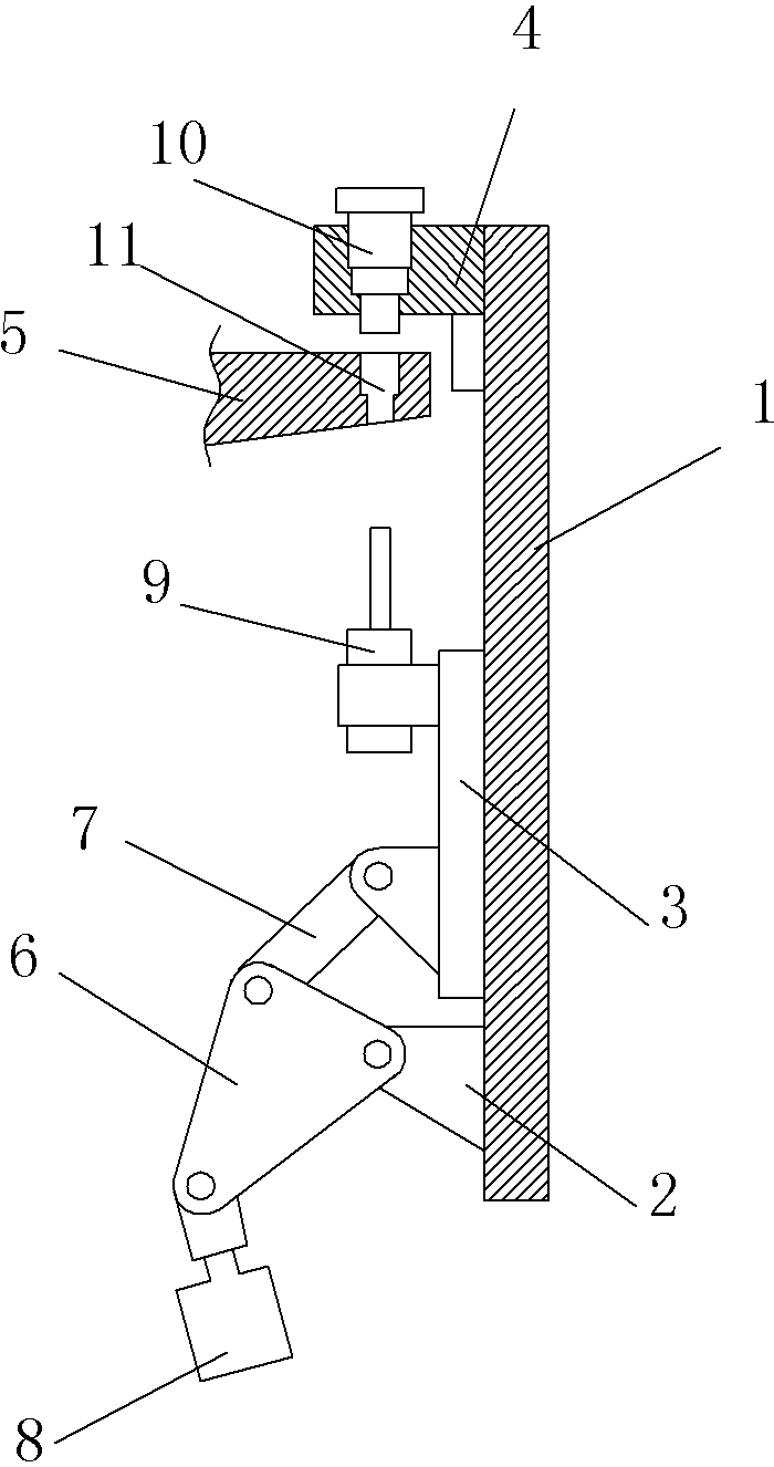
[0008] The reference signs in the accompanying drawings of the specification include: frame 1, pin seat 2, slide block 3, anvil block 4, rotary indexing table 5, triangular toggle lever 6, connecting rod 7, cylinder 8, and pressing tool 9. Upper pressing tool 10, stepped through hole 11.

[0009] Below in conjunction with accompanying drawing and embodiment the technical solution of the present invention is further described:

[0010] Such as figure 1 As shown, a sliding stamping device includes a frame 1 arranged in a vertical direction, on which a pin seat 2, a slider 3 and an anvil 4 are sequentially arranged on the frame 1; the pin seat 2 and the anvil The block 4 is bolted to the frame 1, and the slider 3 is slidably matched with the frame 1; there is a rotary indexing table 5 between the slider 3 and the anvil 4; the pin seat 2 is provided with a triangular elbow Rod 6, the end of triangular toggle lever 6 is respectively hinged with bearing pin seat 2, connecting rod ...


PUM


Abstract

The invention discloses a lathe part for assembling and particularly relates to a sliding stamping device which comprises a machine frame. A vertically-downwards stamping rod is arranged on the upper portion of the machine frame. A stamping head is arranged on a driven end of the stamping rod. A driving end of the stamping rod is connected with a piston rod of a hydraulic cylinder. A supporting device for supporting a rotating working table is arranged on the lower portion of the machine frame below the stamping head. The supporting device comprises a supporting base and a cushion block which is arranged on the supporting base. The bottom of the supporting base is connected with an output shaft of a gas cylinder. A trigger switch is arranged on one side of the stamping rod on the machine frame. A stirring piece which triggers the trigger switch is arranged on the stamping rod. The trigger switch is electrically connected with the gas cylinder. According to the technical scheme, the sliding stamping device is simple in structure and stable in working.

Description

technical field [0001] The invention relates to a machine tool component for assembly, in particular to a sliding stamping device. Background technique [0002] Mechanical tooling is very common in the field of machinery. In the machinery manufacturing industry, a large number of workpieces need to be assembled, but the efficiency of manual assembly is low, and the assembly quality cannot be guaranteed. Contents of the invention [0003] The technical problem to be solved by the present invention is the shortcomings of manual feeding and low assembly efficiency in the prior art, [0004] In order to solve the above-mentioned technical problems, a sliding stamping device includes a frame set in a vertical direction, on which a pin seat, a slider and an anvil are sequentially arranged from bottom to top; The frame is fixedly connected, and the slider is slidingly matched with the frame; there is a rotary indexing table between the slider and the anvil; a triangular toggle i...

Claims


Application Information

Patent Timeline
Patent Type & Authority Applications(China)
IPC IPC(8): B21D39/00
Inventor 严米琪
Owner CHONGQING ZHIRUIDE TECH
Learn More