
Novel uninterrupted power supply method and uninterrupted power source system

A power supply method and power system technology, which is applied in the direction of emergency power supply arrangements, electrical components, circuit devices, etc., can solve the problems of long charging time, short service life of batteries, and high environmental conditions, and achieve huge application potential and economic benefits.

Active Publication Date: 2014-03-19
中科储能(北京)咨询有限公司
View PDF3 Cites 5 Cited by
  • Summary
  • Abstract
  • Description
  • Claims
  • Application Information

AI Technical Summary

Problems solved by technology

The battery has the disadvantages of short service life, long charging time, incomplete discharge, short maintenance cycle, and high environmental conditions. More importantly, the production process of the battery and the treatment process of the used battery are accompanied by pollution.
Flywheel energy storage can achieve fast response and high efficiency, but it needs to be used in conjunction with an internal combustion engine

Method used


Image

  • Novel uninterrupted power supply method and uninterrupted power source system
  • Novel uninterrupted power supply method and uninterrupted power source system

Examples


Embodiment 1

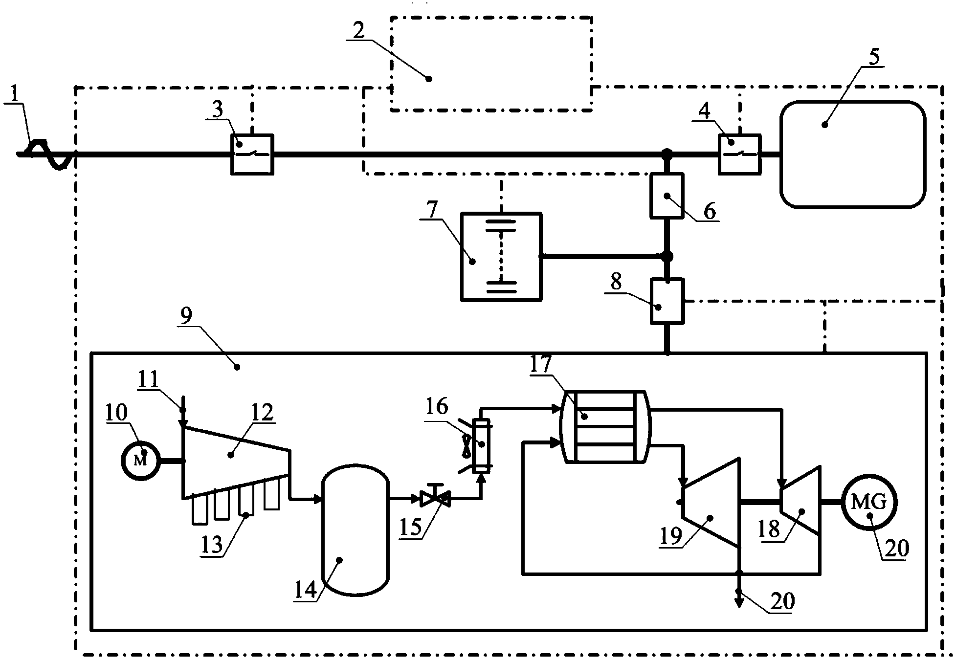
[0032] figure 1 It is a structural schematic diagram of Embodiment 1 of the uninterrupted power supply method and power supply system of the present invention. The monitoring and control unit 2 monitors the working status of each unit in real time (the dotted line in the figure is the monitoring connection line). The monitoring and control unit 2 is connected with the supercapacitor unit 7 and the compressed air power unit 9 through the control circuit, and the monitoring and control unit 2 which is always in the working state is used to dynamically monitor the mains 1, the supercapacitor unit 7 and the compressed air power unit 9 in real time. working status.

[0033] When the mains 1 works normally, the mains 1 inputs energy to the supercapacitor 7 and the heat storage and heat exchange unit 17, and at the same time drives the motor 10 to drive the compressor 12 to compress the air 11 and store it in the air storage tank 14. The component 13 is a compressed air Interstage a...

Embodiment 2

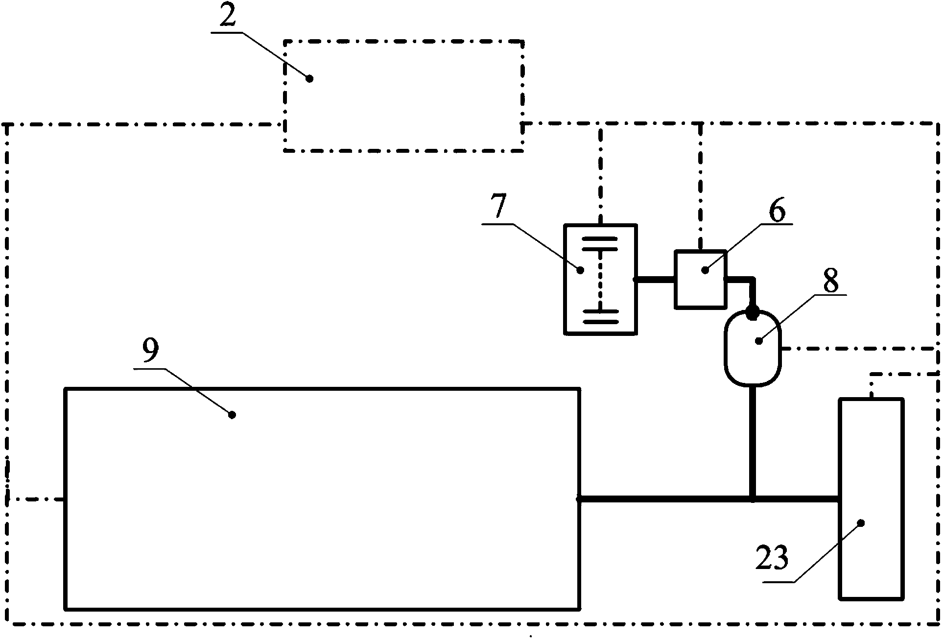
[0035] figure 2 It is a schematic structural diagram of Embodiment 3 of the uninterruptible power supply system of the present invention. This embodiment is a mobile power system, which can be used as vehicle power and the like. Its power source is a compressed air power unit 9, and the compressor therein is not included in this embodiment; and it has two situations including heat storage unit and not including heat storage unit; Stored electrical energy or other forms of heat energy; when the heat storage unit is not included, there are air coolers before and between the expanders, which use ambient energy to heat the gas before each stage expands. The power generated by the power unit 9 is mainly output in the form of shaft work, and the moving power is provided by the rotating wheel 23. When the power system needs to decelerate and brake, the shaft work of the power system unit 9 consumes torque by driving the motor part 8 to achieve braking. For the purpose of driving, t...


PUM


Abstract

The invention discloses a novel uninterrupted power supply method and an uninterrupted power source system. The uninterrupted power source system mainly comprises a super capacitor energy storage unit, a compressed air power unit and a monitoring and control unit. When the commercial power supplies power normally, electric power is stored in the super capacitor and the compressed air power unit; when interruption of the electric power occurs, the super capacitor rapidly responds to supply power for electric equipment, and the compressed air power unit further starts to realize continuous long-time power supply; when the commercial power recovers to a normal state, the electrical network electric power is utilized to realize an energy storage process, moreover, compressed air in an air storage tank is supplemented through a compressor. The uninterrupted power source system employs the super capacitor and the compressed air power unit and has advantages of rapid response, low carbon, environmental friendliness, long service life, low maintenance cost and strong adaptation capability.

Description

technical field [0001] The invention relates to an uninterrupted power supply method and a power supply system, in particular to an uninterrupted power supply method and a power supply system coupling commercial power, a supercapacitor and a compressed air power unit. Background technique [0002] Uninterruptible power supply (Uninterruptible Power Supply, UPS) is a power supply equipment including rectification, energy storage, inverter and switch components, which is connected to the grid or local grid as an emergency power supply or backup power supply. When the grid power supply system is interrupted , the device releases the stored electrical energy to achieve continuous power supply and maintain the normal operation of electrical equipment. Uninterruptible power supply has a wide range of applications in industrial, commercial and residential fields, mainly including communication, information technology, computer data center, industrial control, medical treatment, ene...

Claims


Application Information

Patent Timeline
Patent Type & Authority Applications(China)
IPC IPC(8): H02J9/06H02J9/08
Inventor 张新敬盛勇陈海生谭春青
Owner 中科储能(北京)咨询有限公司
Learn More