
Swinging clamping device

A technology of clamping device and jaw, applied in the field of workpiece clamping device

Inactive Publication Date: 2014-03-19
CHONGQING BISHAN AIHUA
View PDF0 Cites 4 Cited by
  • Summary
  • Abstract
  • Description
  • Claims
  • Application Information

AI Technical Summary

Problems solved by technology

[0003] The invention provides a swing clamping device to solve the problem in the prior art that one round trip can only clamp and loosen the workpiece once

Method used


Image

  • Swinging clamping device

Examples


Embodiment Construction

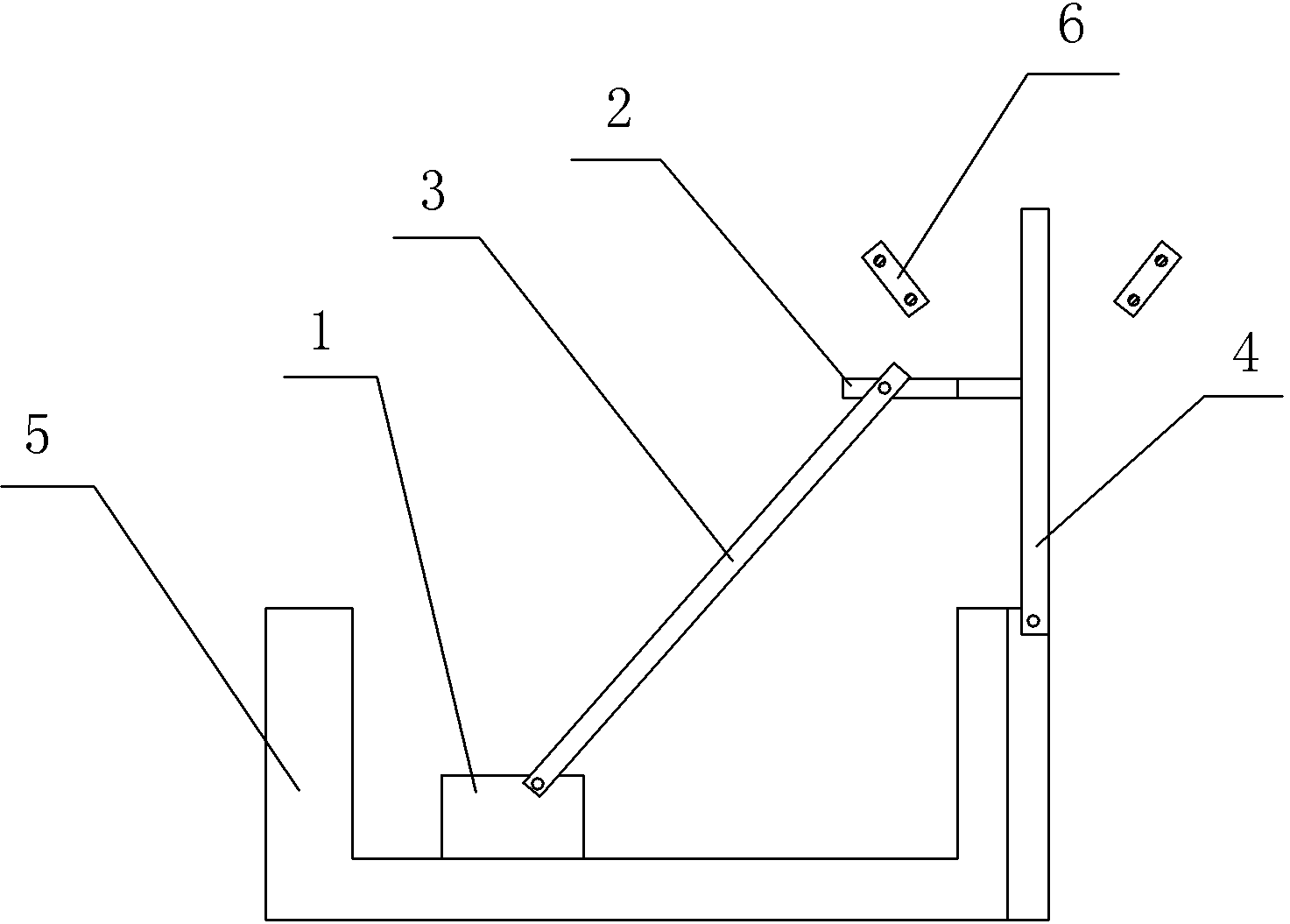
[0009] The reference signs in the accompanying drawings of the description include: jaw 1 , connecting rod 2 , push rod 3 , swing rod 4 , accommodating groove 5 , and block 6 .

[0010] like figure 1 As shown, a swing clamping device in this embodiment includes a frame, a jaw 1, a connecting rod 2, a push rod 3, a swing rod 4 hinged on the frame, and an accommodating groove connected to the frame 5. The jaw 1 is slidingly connected in the accommodation groove 5, the connecting rod 2 is fixedly connected to the swing rod 4, one end of the push rod 3 is hinged with the connecting rod 2, and the other end is hinged with the jaw 1, and the frame is Stoppers 6 are arranged on the left and right sides of the swing rod 4 . The connecting rod 2 is mainly formed by connecting an inner pipe and an outer pipe through threads, and the inner pipe is fully threaded. The jaw 1 is provided with a pressure sensor.

[0011] The working process of this embodiment is as follows: rotate the swi...


PUM


Abstract

The invention discloses a swinging clamping device which comprises a machine frame, a clamping jaw, a connecting rod, a push rod, a swing rod hinged to the machine frame and an accommodating groove connected to the machine frame. The clamping jaw is slidably connected to the accommodating groove, the connecting rod is fixedly connected with the swing rod, one end of the push rod is hinged to the connecting rod, the other end of the push rod is hinged to the clamping jaw, and the machine frame is provided with a check block in the swinging direction of the swing rod. Clamping and loosening of two workpieces can be achieved through a round trip according to the swinging clamping device. The machine frame is provided with the check block in the swinging direction of the swing rod, the check block is used for limiting the sliding limit position of the clamping jaw, and the damage to the workpieces caused by excessive clamping is avoided.

Description

technical field [0001] The invention belongs to the technical field of workpiece clamping devices. Background technique [0002] The clamping device is used to locate and clamp the workpiece, mainly through the reciprocating swing of the jaws. Grippers are divided into forward and return. The existing jaws usually clamp the workpiece in the inbound and release the workpiece in the return. One round trip can only clamp and loosen the workpiece once, resulting in a long time for processing the workpiece. less efficient. Contents of the invention [0003] The invention provides a swing clamping device to solve the problem in the prior art that one round trip can only clamp and loosen workpieces once. [0004] In order to solve the above-mentioned technical problems, the present invention provides the following technical solutions: A swing clamping device, comprising a frame, jaws, connecting rods, push rods, swing bars hinged on the frame, and a housing connected to the fra...

Claims


Application Information

Patent Timeline
Patent Type & Authority Applications(China)
IPC IPC(8): B23Q3/06
CPCB25B11/00
Inventor 袁晴波
Owner CHONGQING BISHAN AIHUA
Learn More