
Stirling heat engine solar heat collector

A technology of solar heat collectors and heat engines, which is applied to solar heat collectors, solar heat collectors using working fluids, and solar thermal energy, etc., which can solve the problems of short service life, uneven heating on the surface of solar heat collectors, and inability to heat uniformly Stable transmission to heat exchange tubes and other issues, to achieve long service life, stable work, and reduce heat loss

Active Publication Date: 2014-03-12
斯特林威索AB
View PDF5 Cites 7 Cited by
  • Summary
  • Abstract
  • Description
  • Claims
  • Application Information

AI Technical Summary

Problems solved by technology

[0004] In order to overcome the disadvantages of uneven heating on the surface of the solar heat collector in the prior art, short service life, and the inability to transfer heat to the heat exchange tube uniformly and stably, the present invention provides a uniform and stable heat transfer tube. Heat exchange tubes for Stirling heat engines, Stirling heat engine solar collectors to improve the working efficiency and service life of Stirling heat engines

Method used


Image

  • Stirling heat engine solar heat collector
  • Stirling heat engine solar heat collector
  • Stirling heat engine solar heat collector

Examples


Embodiment Construction

[0020] The present invention will be further described below in conjunction with accompanying drawing and specific embodiment:

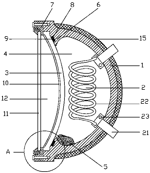
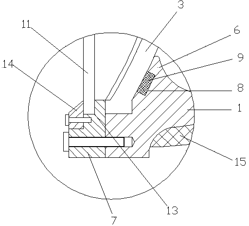
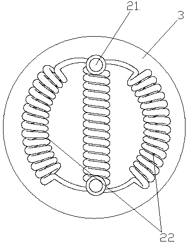
[0021] Such as figure 1 A Stirling heat engine solar collector shown includes a heat collecting cover 1 and a heat exchange tube 2 arranged in the heat collecting cover. In this embodiment, a heat collecting plate 3 is provided at the open end of the heat collecting cover. The heat collecting cover 1 is a hemisphere, the heat collecting plate 3 is a spherical plate, the heat collecting plate 3 is made of cermet, and its outer surface is provided with a high temperature resistant coating 10, the high temperature resistant coating is an alumina coating, and the heat collecting plate The outer convex surface of 3 faces the bottom of the heat collecting cover 1, and a closed heat collecting chamber 4 is formed between the heat collecting plate and the heat collecting cover. The heat collecting chamber 4 is provided with metal sodium 5, and the heat c...


PUM


Abstract

The invention discloses a Stirling heat engine solar heat collector which comprises a heat collecting cover and a heat-exchanger tube arranged in the heat collecting cover. A heat collecting plate is arranged at the opening end of the heat collecting cover, a closed heat collecting cavity is defined by the heat collecting plate and the heat collecting cover, metallic sodium is arranged in the heat collecting cavity, the heat collecting cavity is filled with inert gas, and the two ends of the heat-exchanger tube respectively extend out of the heat collecting cover from the bottom of the heat collecting cover and are communicated with the heat end and the cold end of a Stirling air cylinder respectively. The heat collecting cover is in a hemispheroid shape, the heat collecting plate is a spherical surface plate, the outwards-protruding face of the heat collecting plate is towards the bottom of the heat collecting cover, the inner wall of the opening end of the heat collecting cover is extended to form a supporting ring, and the outer lateral face of the supporting ring is fitted with the periphery of the inner side of the heat collecting plate in a supported mode. The Stirling heat engine solar heat collector accordingly has the advantages that the temperature in the heat collecting cover is even, the heat absorption rate of the heat-exchanger tube is high, a Stirling heat engine can stably work, the service life is long, the temperature at the position around the inner lateral face of the heat collecting plate can be kept even through sodium fog, and the service life shortening caused by the local high temperature of the heat collecting plate is prevented.

Description

technical field [0001] The invention relates to the technical field of Stirling heat engines, in particular to a solar collector for Stirling heat engines. Background technique [0002] The Stirling engine is a unique heat engine, because the theoretical efficiency is almost equal to the theoretical maximum efficiency, called the Carnot cycle efficiency, so the Stirling engine has a wide range of applications in new energy power generation and military industry. The Stirling engine generates power by expanding the gas when it is heated and compressing it when it is cold. This is an external combustion engine that burns fuel continuously, expands hydrogen (or helium) as a power gas to move the piston, and expands the gas in the cold chamber. Cooling, such a cycle process is carried out repeatedly, and the outer end of the piston handle is connected to the crank connecting rod mechanism, thereby driving the three-phase generator to rotate and converting mechanical energy into ...

Claims


Application Information

Patent Timeline
IPC IPC(8): F24J2/24F24J2/46F24S10/70
CPCY02E10/44
Inventor 万斌
Owner 斯特林威索AB
Learn More