
Cryogenic fixed ball valve

A fixed ball valve, low temperature technology, applied to the valve details, valve device, valve shell structure, etc., can solve the problems of poor effect, easy leakage, valve sealing effect, etc., to achieve simple structure, timely pressure relief, and good sealing effect leaked effect

Active Publication Date: 2017-01-25
KCM VALVE
View PDF7 Cites 0 Cited by
  • Summary
  • Abstract
  • Description
  • Claims
  • Application Information

AI Technical Summary

Problems solved by technology

[0009] In order to overcome the deficiencies of the background technology, the present invention provides a low-temperature fixed ball valve, which mainly solves the problem that the pressure relief method of the valve cavity in the existing low-temperature fixed ball valve is not effective or will affect the sealing of the valve and is prone to leakage.

Method used


Image

  • Cryogenic fixed ball valve
  • Cryogenic fixed ball valve
  • Cryogenic fixed ball valve

Examples


Embodiment Construction

[0026] Embodiments of the present invention will be further described below in conjunction with accompanying drawings:

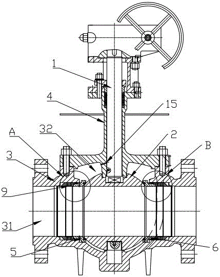
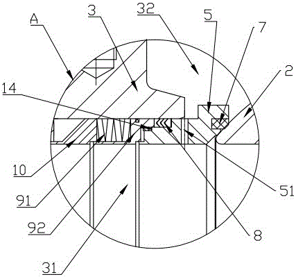
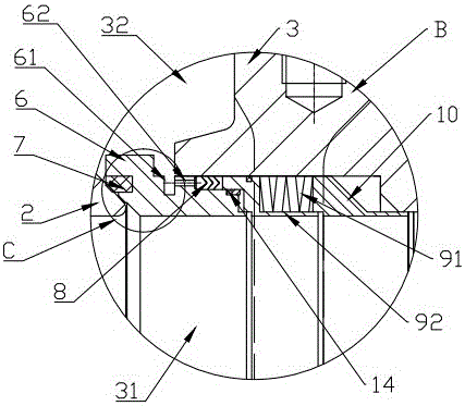
[0027] like figure 1 , figure 2 and image 3 As shown, a low-temperature fixed ball valve includes a valve body 3, a ball body 2, a valve stem 1, and a valve cover 4. The valve body 3 is provided with a flow channel 31, and the ball body 2 is arranged in the flow channel 31 of the valve body 3. , linked with the valve stem 1; the two sides of the sphere 2 are provided with a valve seat support ring, a valve seat 7 is provided between the valve seat support ring and the sphere 2, and a valve seat 7 is provided between the valve seat support ring and the valve body 3 There is a sealing component 8; the valve seat support ring, the valve seat 7, the valve cover 4, the valve body 3 and the outer ring of the ball 2 constitute the valve body cavity 32;

[0028] The first valve seat support ring 5 on one side of the ball 2 is provided with a pressure relief hol...


PUM


Abstract

The invention provides a low-temperature fixed ball valve which mainly solves the problems that the pressure relief effect of a central valve cavity of an existing low-temperature fixed ball valve is bad so that the sealing effect of the valve may be influenced and the valve is prone to leakage. The low-temperature fixed ball valve is characterized in that a first valve seat support ring is provided with a pressure relief hole. The central valve cavity is communicated with a fluid passage in one side of a ball body through the pressure relief hole. The low-temperature fixed ball valve has the advantages that when the pressure in the central valve cavity rises abnormally, the pressure can be timely and fully released into the fluid passage, so that the pressure in the central valve cavity keeps the same as the pressure in the fluid passage; therefore, the low-temperature fixed ball valve is simple in structure, timely in pressure relief, good in pressure relief effect, good in sealing effect and free from leakage, and the sealing effect on the valve will not be influenced.

Description

technical field [0001] The invention relates to a ball valve, in particular to a low-temperature fixed ball valve used in LNG projects and other low- and ultra-low temperatures. Background technique [0002] At this stage, with the rapid development of petroleum, chemical and gas industries, especially liquefied natural gas (LNG) is rapidly rising as a new energy source. Statistics show that the current consumption of natural gas in my country is far below the world average. With climate change and my country's energy transformation, the demand for fast-growing natural gas is increasing. However, as one of the important supporting equipment for LNG, the design and manufacturing technology of ultra-low temperature valves for liquid cargo systems are still monopolized by foreign countries. At present, the ultra-low temperature valves on the five LNG ships built by Hudong Zhonghua are all imported products, which greatly reduces the added value and core competitiveness of my c...

Claims


Application Information

Patent Timeline
Patent Type & Authority Patents(China)
IPC IPC(8): F16K5/06F16K5/08
CPCF16K5/0689F16K5/201F16K27/067
Inventor 吴业飞章成选
Owner KCM VALVE
Learn More