
Muffler assembly with siphon tube

A siphon tube and component technology, applied in the field of muffler components, can solve problems such as increased noise, discoloration of parking areas, increased weight or cost, etc., to achieve the effects of worsening noise problems, less corrosion, and long service life

Active Publication Date: 2014-03-12
GM GLOBAL TECH OPERATIONS LLC
View PDF6 Cites 8 Cited by
  • Summary
  • Abstract
  • Description
  • Claims
  • Application Information

AI Technical Summary

Problems solved by technology

This causes increased noise
Also, when the vehicle is parked, condensation can escape through the drain hole, discoloring the parking area
Alternatively, the housing can be made of a more corrosion-resistant material, but this adds weight or cost
The design of the discharge system with valves or injection pumps can be complicated and costly

Method used


Image

  • Muffler assembly with siphon tube
  • Muffler assembly with siphon tube
  • Muffler assembly with siphon tube

Examples


Embodiment Construction

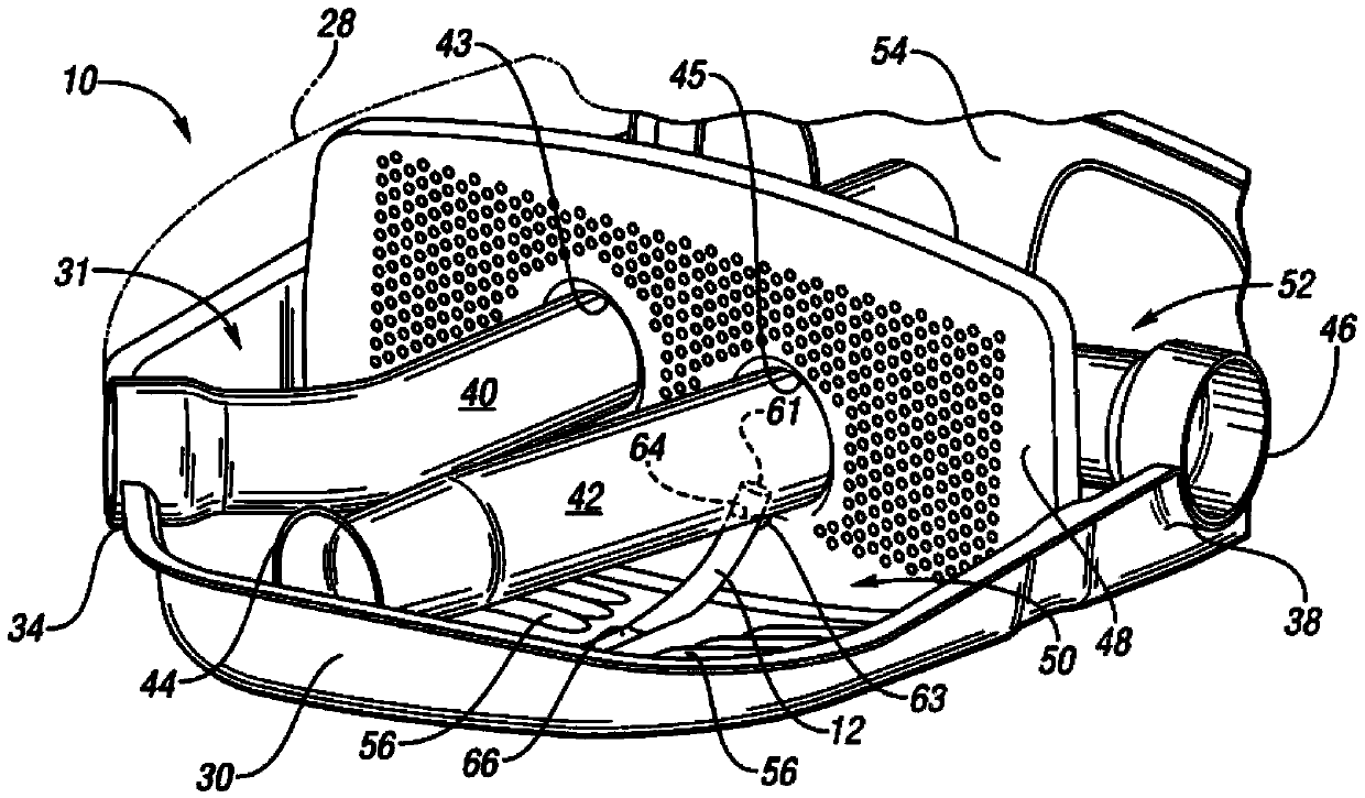
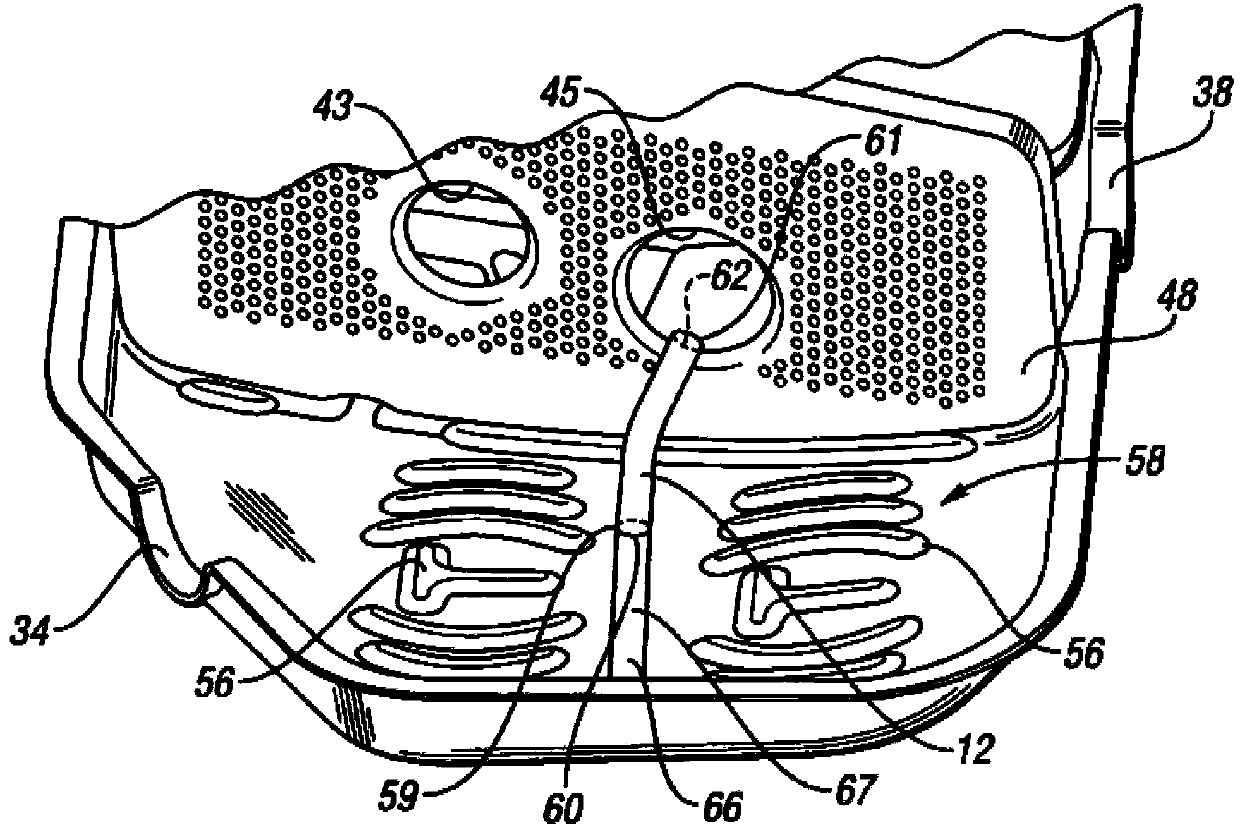
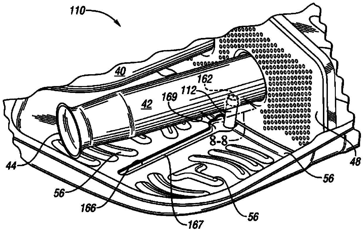
[0014] Referring to the drawings, wherein like reference numerals represent like parts throughout the several views, figure 1 A muffler assembly 10 is shown having a siphon 12 specifically designed to remove condensate from the muffler assembly 10 as further described herein. Specifically, the muffler assembly 10 is designed such that condensate collects below the siphon tube and is discharged from the muffler assembly 10 through the siphon tube 12 when the pressure differential across the siphon tube 12 reaches a predetermined level.

[0015] The muffler assembly 10 is part of an exhaust system 14 of a vehicle 16, such as Figure 5 shown. The vehicle 16 has front wheels 18 and rear wheels 20 . The powertrain 22 includes an engine 24 operatively connected to the front wheels 18 through a transmission 26 for propelling the vehicle. Exhaust system 14 extends from engine 24 to treat engine exhaust prior to expelling the exhaust to the atmosphere. One or more exhaust treatment...


PUM


Abstract

A muffler assembly for a vehicle includes a housing at least partially defining an internal cavity and having an inlet and an outlet. The muffler assembly includes an outlet pipe that has an inlet end open to the internal cavity and an outlet end open at the outlet of the housing. A siphon tube is in the internal cavity and has an inlet opening adjacent an inner surface of the housing and an outlet opening in fluid communication with the outlet pipe between the inlet end and the outlet end of the outlet pipe. The siphon tube is configured to remove condensate from the internal cavity when a predetermined pressure differential is established between the inlet opening and the outlet opening.

Description

technical field [0001] The invention generally includes muffler assemblies for vehicles. Background technique [0002] Muffler assemblies are commonly used in vehicle exhaust systems to reduce the noise associated with the exhaust emitted by the engine. The muffler assembly has a housing through which exhaust is expelled from an inlet to an outlet. Condensate from the exhaust tends to collect inside the housing. Condensation will corrode the housing if not drained. Means for draining the condensate include providing drain holes in the bottom of the housing. This causes increased noise. Additionally, condensation can escape through the drain hole when the vehicle is parked, discoloring the parking area. Alternatively, the housing could be made of a more corrosion resistant material, but this would add weight or cost. The design of the discharge system with valves or injection pumps can be complicated and costly. Contents of the invention [0003] A muffler assembly f...

Claims


Application Information

Patent Timeline
Patent Type & Authority Applications(China)
IPC IPC(8): F01N13/00
CPCF01N1/083F01N2240/22F01N1/02F01N2470/30F01N2490/08
Inventor C.张B.莫尔曼W.王C.S.海斯Q.E.陈
Owner GM GLOBAL TECH OPERATIONS LLC
Learn More