Universal adjusting centering clamping device

A clamping device and universal technology, applied in the field of universal adjustment and centering clamping device, can solve the problems of high processing cost and use cost, low processing efficiency, easy to scratch tiles, etc., to reduce processing cost and use Cost and positioning process save time and effort, and the effect of low development cycle

Inactive Publication Date: 2014-03-12
SHENYANG LIMING AERO-ENGINE GROUP CORPORATION
View PDF5 Cites 5 Cited by
  • Summary
  • Abstract
  • Description
  • Claims
  • Application Information

AI Technical Summary

Problems solved by technology

[0003] There are mainly two traditional methods for processing the inner and outer tiles of the engine. The first method is to use an expensive CNC machining center for processing. Although the CNC machining center can meet the processing needs of the inner and outer tiles of the engine, its processing cost and use The cost is very high, which leads to the low utilization rate of this method; the second method is to use ordinary lathes for processing, but before processing, it is necessary to design and manufacture corresponding special fixtures for the inner and outer tiles of the engine, and the scope of application of special fixtures Single, at the same time, the utilization rate of the special fixture is very low, and the angle and position of the inner and outer tiles of the engine cannot be adjusted. For the studs, only one can be processed at a time. To process other studs, the tiles must be removed first. , readjust the position of the tiles, and clamp the tiles again. This process is not only time-consuming and laborious, but also easily scratches the tiles during the clamping process, resulting in a high defective rate of the product, and it is difficult for ordinary lathes to pass special fixtures. Improve the processing efficiency of the inner and outer tiles of the engine. This low processing efficiency will directly affect the overall development cycle of the aero-engine

Method used


Image

  • Universal adjusting centering clamping device
  • Universal adjusting centering clamping device
  • Universal adjusting centering clamping device

Examples


Embodiment Construction

[0018] The present invention will be further described in detail below in conjunction with the accompanying drawings and specific embodiments.

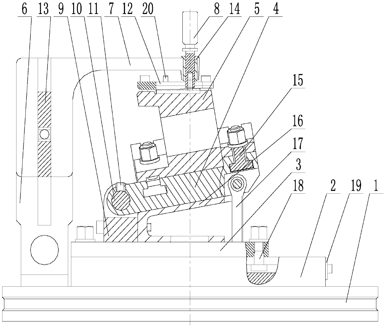
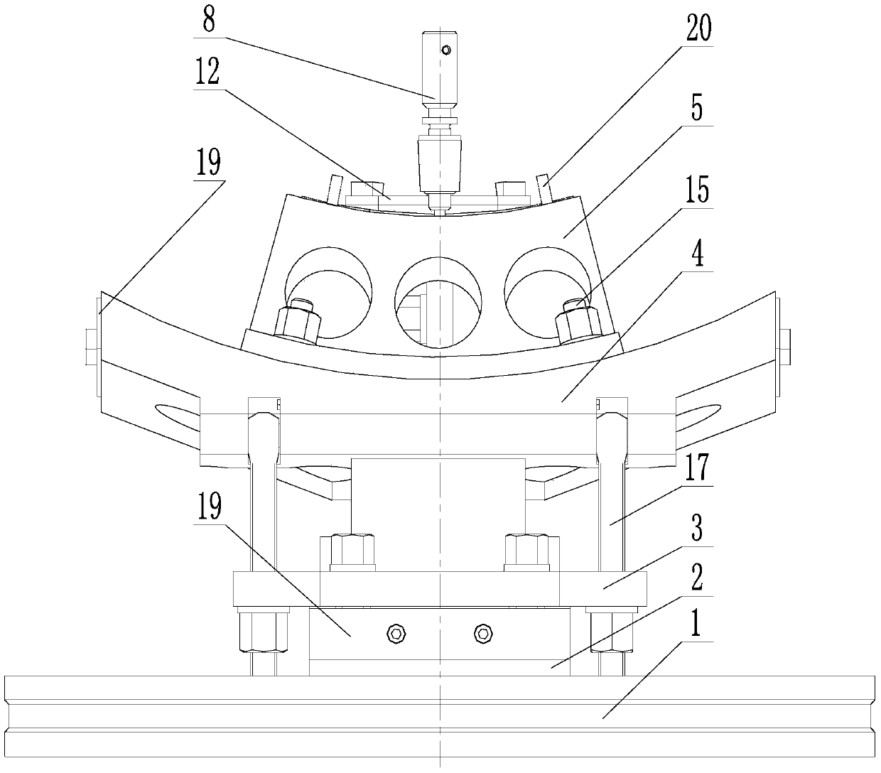
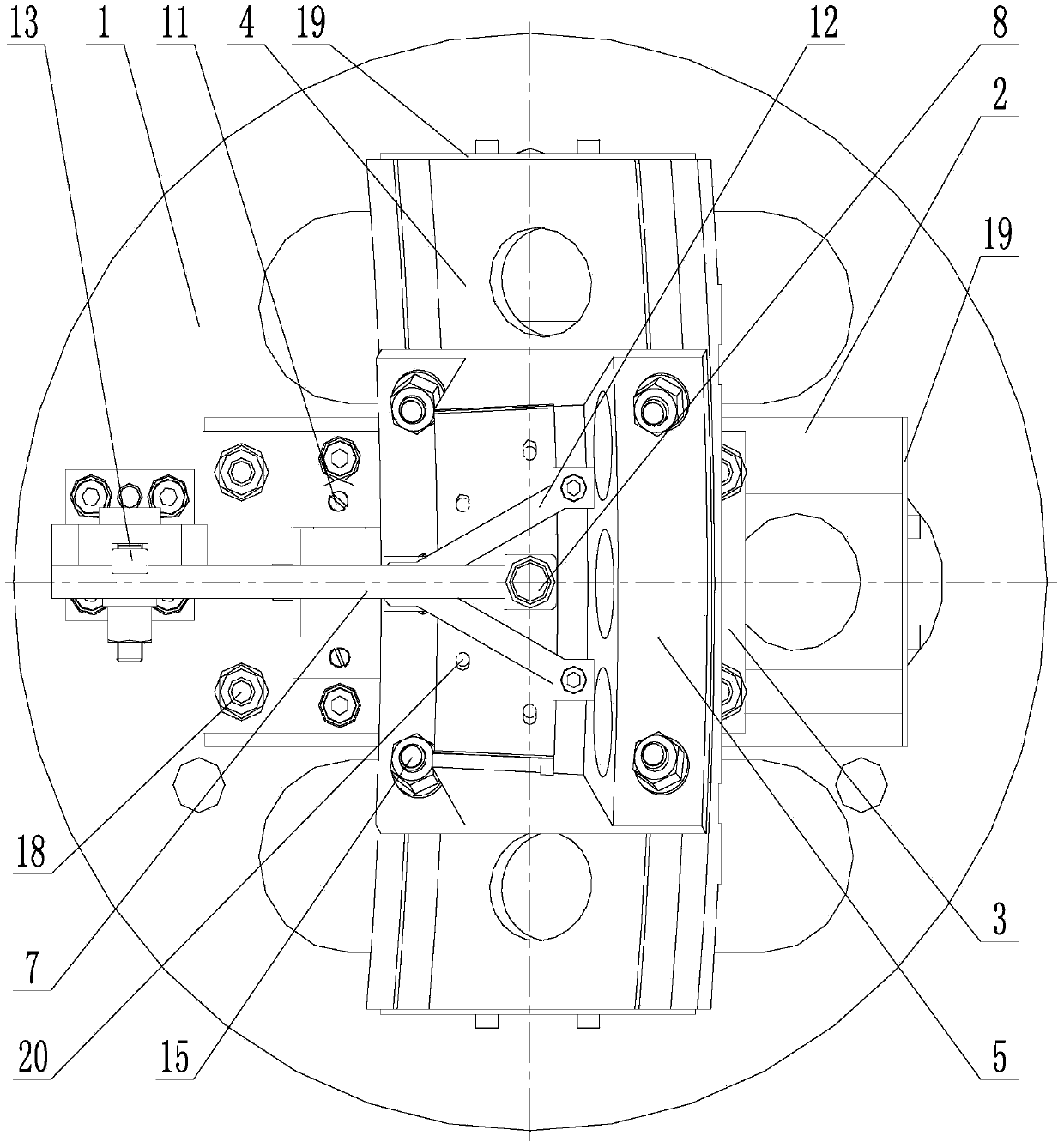
[0019] Such as figure 1 , 2 , 3, a universal adjustment centering clamping device, including a base 1, a plane track plate 2, a plane slide 3, an arc track plate 4, an arc slide 5, a bracket 6 and a center arm 7, The base 1 is configured as a disc-shaped structure, the plane track plate 2 is fixed on the base 1, and two mutually parallel T-shaped grooves are arranged on the upper end of the plane track plate 2; the plane slide seat 3 is arranged on a plane The upper part of the track plate 2 is slidably matched; four second T-bolts 18 are installed on the plane slide 3, and the plane slide 3 is connected with the plane track plate 2 through the second T-bolts 18, and every two The T-shaped head of the second T-shaped bolt 18 is located in the T-shaped groove of a plane track plate 2; 10 is connected with the rotating shaft fixed se...


PUM


Abstract

The invention provides a universal adjusting centering clamping device, and belongs to the technical field of aero-engine part manufacturing. A base of the device is of a disc-shaped structure, a plane rail plate provided with a T-type groove is fixedly arranged on the base, and a plane sliding base is matched with the plane rail plate in a sliding mode through a T-type bolt; one end of an arc rail plate provided with a T-type groove is connected with the base through a rotary shaft and a rotary shaft fixing base, and the other end of the arc rail plate is connected with the plane sliding base through a hinge bolt; an angle cushion block is arranged between the arc rail plate and the plane sliding base; an arc sliding base is matched with the arc rail plate in a sliding mode through a T-type bolt, the top of the arc sliding base is provided with a pressing plate, and the pressing plate is connected with the arc sliding base through a bolt; a support is fixedly disposed on the base, and a center supporting arm is matched with the support in a sliding mode through a sliding key; the center supporting arm is provided with a center positioning plug-pin, the axis center line of the center positioning plug-pin and the axis center line of the base are overlapped, and the lower end of the center positioning plug-pin is the positioning end and corresponds to the top end of the arc sliding base.

Description

technical field [0001] The invention belongs to the technical field of manufacturing aero-engine parts, in particular to a universally adjustable centering clamping device. Background technique [0002] In the development process of aero-engines, the manufacturing and processing efficiency of its components often determines the overall development cycle of aero-engines, especially some parts with curved surfaces, and the angle and position of the parts need to be adjusted during processing. The processing difficulty is higher than that of parts with a flat surface. The most typical parts with a curved surface are the inner and outer tiles of the engine, and several studs that need to be processed are distributed on the curved surface. [0003] There are mainly two traditional methods for processing the inner and outer tiles of the engine. The first method is to use an expensive CNC machining center for processing. Although the CNC machining center can meet the processing nee...

Claims


Application Information

Patent Timeline
Patent Type & Authority Applications(China)
IPC IPC(8): B23Q3/00
CPCB23Q3/00
Inventor 彭会文赵西松曾庆国陈宏海
Owner SHENYANG LIMING AERO-ENGINE GROUP CORPORATION
Why Eureka
Try Eureka