
Plate shearing machine

A technology of shearing machine and shearing device, which is applied in the direction of shearing machine, shearing device, and accessory device of shearing machine, etc., can solve the problems of increased production cost and inconvenient operation, and achieve the goal of convenient and practical, easy cutting and adjustment Effect

Inactive Publication Date: 2014-03-12
天津宏泰空调净化设备有限责任公司
View PDF0 Cites 7 Cited by
  • Summary
  • Abstract
  • Description
  • Claims
  • Application Information

AI Technical Summary

Problems solved by technology

[0003] In the prior art, the shearing machine has been able to efficiently complete the cutting work of metal sheets, but for cutting different types of sheets, before each cutting, it is necessary to recalculate according to the length of the cutting and the speed of the conveyor belt. It is very inconvenient to operate when the knife is out of the gap
In addition, after cutting, due to the lack of corresponding equipment for separation, in order not to affect the processing of subsequent processes, it is often necessary to increase the separation process, which increases the production cost

Method used


Image

  • Plate shearing machine
  • Plate shearing machine

Examples


Embodiment Construction

[0017] The specific implementation manners of the present invention will be briefly described below in conjunction with the accompanying drawings.

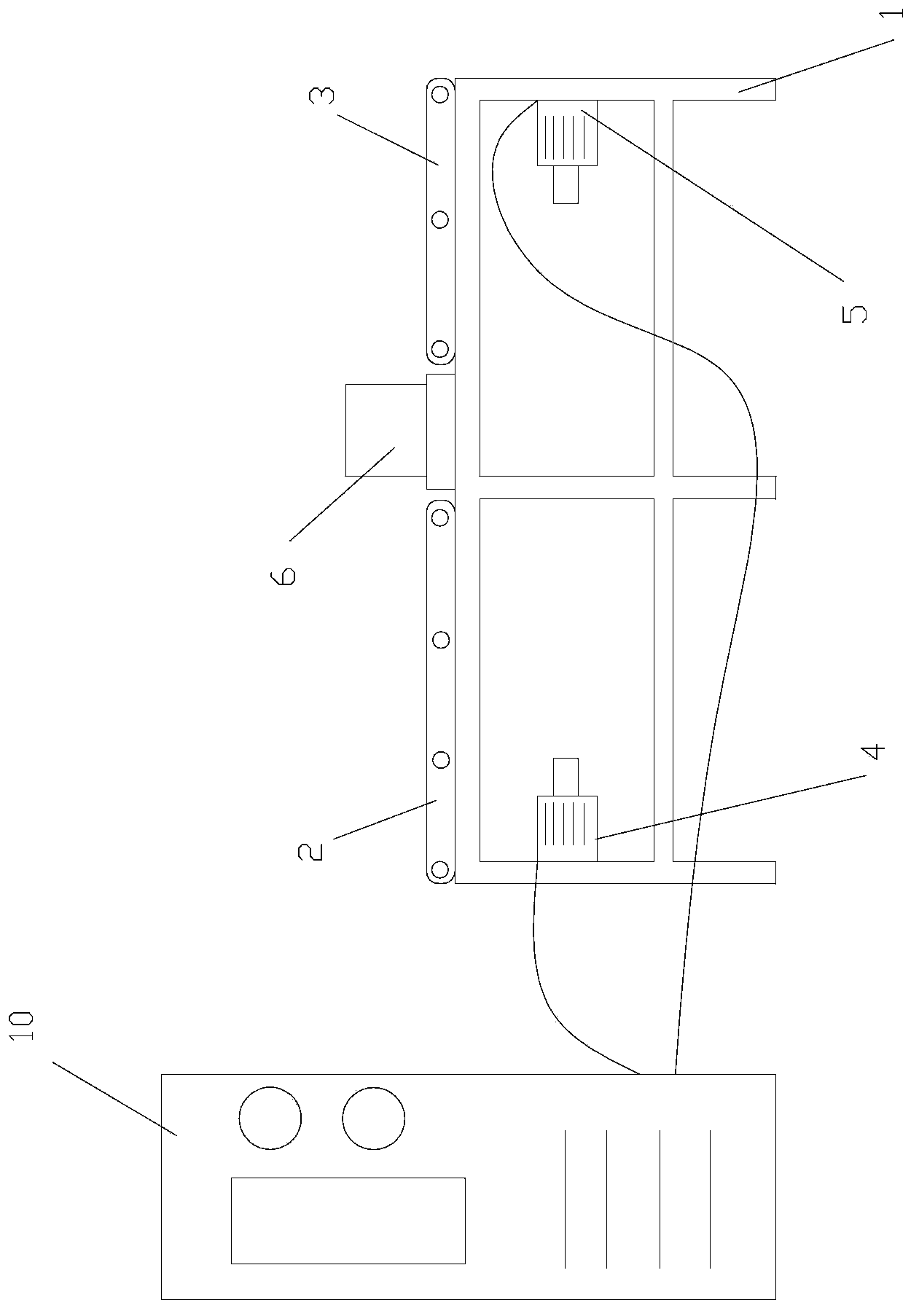
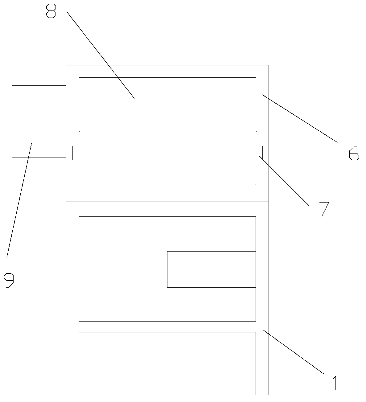
[0018] Such as figure 1 , figure 2 As shown, a shearing machine includes a main body 1 and a shearing device 6 , and the shearing device 6 is located on the main body 1 . It also includes a first conveyor belt 2 and a second conveyor belt 3 located on the main body 2, and the first conveyor belt 2 and the second conveyor belt 3 are located at two ends of the shearing device 6 respectively. The main body 1 is provided with a first motor 4 connected to the first conveyor belt 2 ; the main body 1 is provided with a second motor 5 connected to the second conveyor belt 3 . The shearing device 6 is provided with a cutter 8, and the cutter 8 is made of Cr12MoV steel. The side end of the shearing device 6 is provided with a distance measuring device 7, and the distance measuring device 7 is an infrared distance measuring device. A hy...


PUM


Abstract

The invention provides a plate shearing machine. According to the technical scheme, the plate shearing machine comprises a body and a shearing device which is located above the body. The plate shearing machine is characterized by further comprising a first conveyor belt and a second conveyor belt. The first conveyor belt and the second conveyor belt are located above the body. The first conveyor belt and the second conveyor belt are located at the two ends of the shearing device respectively. A first motor is arranged on the body and connected with the first conveyor belt. A second motor is arranged on the body and connected with the second conveyor belt. The plate shearing machine has the advantages that separating metal plates can be achieved with the shearing machine; in addition, as a distance measuring device is added, the plates with different lengths can be easily cut and adjusted; a traditional conveyor belt is divided into the two conveyor belts, the plates can be successively separated after being cut and utilization of follow-up equipment is facilitated.

Description

technical field [0001] The invention relates to the technical field of sheet metal processing and manufacturing, in particular to a shearing machine. Background technique [0002] The shearing machine uses the moving upper blade and the fixed lower blade to apply shearing force to metal sheets of various thicknesses with a reasonable blade gap, so that the sheets are broken and separated according to the required size. The shearing machine can be divided into: pedal type, mechanical shearing machine type, hydraulic pendulum shearing machine and so on. Shears are often used to cut sheet blanks with straight edges. The shearing process should be able to ensure the straightness and parallelism requirements of the sheared surface of the sheared sheet, and minimize the distortion of the sheet to obtain high-quality workpieces. [0003] In the prior art, the shearing machine has been able to efficiently complete the cutting work of metal sheets, but for cutting different types o...

Claims


Application Information

Patent Timeline
Patent Type & Authority Applications(China)
IPC IPC(8): B23D15/06B23D33/00
Inventor 王梓腾
Owner 天津宏泰空调净化设备有限责任公司
Learn More